Hi TI team,
I have a typical H-bridge for a switching converter with two UCC27211A (one for leading/lagging leg) sharing the same Vdd. We are intentionally using the UVLO function to prevent switching by reducing the Vdd from 12V to 6V when the PCBA is in a reset state. I expect that when Vdd is 6V, there should be no output PWM from the gate driver since the output will become Hi-Z.
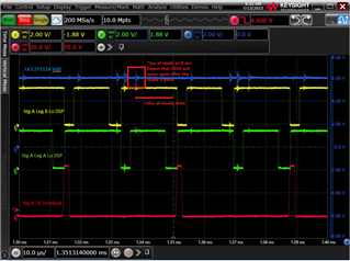
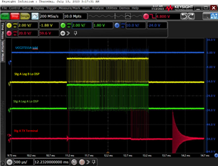
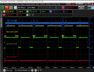
However, during my testing, when the Vdd is 6V and my DSP is driving the input PWM, I see that the gate driver output occasionally turn on. Please see the attached scope shots:
Zoomed in:
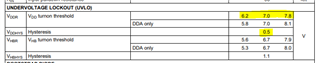
I am aware that there is some hysteresis + component variation based on the data sheet here:
I have 3 questions:
1. Is the UVLO turn off threshold threshold after the gate driver chip is turned on equal to Vddr - Vddhys = 6.5 (typical)?
2. Is the noise seen in these scope shots sufficient to turn on the gate driver for a short duration?
3. Our existing PCBA can only reduce the Vdd to a minimum of 6V so we will not be able to cover the entire range of component variation on Vddr lockout threshold. Could you provide the distribution curve of what the min/typ/max spread looks like for this parameter?
Thanks,
Rick