This thread has been locked.

If you have a related question, please click the "Ask a related question" button in the top right corner. The newly created question will be automatically linked to this question.

LMR36520: Low side current limit

Part Number: LMR36520

Hello Support team,

My customer ask the questions. Could you support?

*Does low side current limit occur after high side current limit hit? Or low side current limit can work without high side current limit hit?

As example, in case IOUT:2A and ILripple : 0.2A, this never hit ISC threshold, but, ILS_LIMIT is min 1.8A, does low side FET keep on until inductor current reach to 1.8A?

*How does LMR36520 change the mode from PFM to PWM and from PWM to PFM? zero cross detector threshold IL_ZC 0.04A?

Thanks,

Koji Ikeda

  • Hi Ikeda-san.

    We will look into this and get back to you.

    Thanks,

    Andrew

  • Hi Ikeda-san,

    Sorry for the delay.

    -In general, if the high side current limit is not triggered, the low side current limit will not be triggered. However, in theory, the low side current limit CAN work without the high side current limit, but it has certain limitations such as being susceptible to ground disturbances and not being able to detect fault conditions such as a short between the power supply and ground.

    -A converter operating in power save mode uses PFM at light load currents and pulse width modulation (PWM) at heavier load currents. While in PFM mode, the converter only operates when the output voltage is below the nominal output voltage. When this happens, the converter begins switching until the output voltage is regulated to a typical value between the nominal output voltage and 0.8% above the nominal output voltage. During the period where the converter is powered down, all unnecessary internal circuitry is turned off to reduce the IC's quiescent current. This control method significantly reduces the quiescent current to a typical value of 20 µA, which results in higher efficiency at light loads. In contrast to PWM mode, in which the converter is continuously switching, PFM mode allows the converter to switch in short bursts.

    Please find a link to a pdf with a more in-depth explanation of changing from PWM to PFM below and refer to Figures 3 and 4 for visual aides:

    https://ti.com/lit/an/slva236a/slva236a.pdf?ts=1689619321386&ref_url=https%253A%252F%252Fwww.google.com%252F

    Hope this helps,
    Daniel 

  • Daniel-san,

    Thank you for your support.

    They need transition point or threshold, from PWM to PFM and from PFM to PWM. Could you support? Is this zero cross detector threshold IL_ZC 0.04A?

    Thanks,

    Koji Ikeda

  • Hi Ikeda-san,

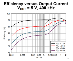
    The transition point can be estimated using this curve found on page one of the data sheet


    The points marked with the arrows are the transition from PFM to PWM. 
    Keep in mind, this transition point is largely determined by your component values, component tolerances, and I/O requirements. The transition points shown in this graph are typical values. 

    The zero cross detector threshold IL_ZC is used for diode emulation at light load to maximize efficiency.

    Best,
    Daniel Louis 

  • Daniel-san,

    Thank you for your support. Please let me confirm, I feel that your highlight on efficiency cure is transition from PWM to DCM (diode emulation), is this transition from PWM to PFM? They would like to know load current point when the sw frequency changes correctly.

    Thanks,

    Koji Ikeda

  • Daniel-san,

    What do you mean? Do you mean this transition is from PWM to PFM? 

    Thanks,

    Koji Ikeda