This thread has been locked.

If you have a related question, please click the "Ask a related question" button in the top right corner. The newly created question will be automatically linked to this question.

LM7480-Q1: What is the quiescent current in CS configuration

Part Number: LM7480-Q1

What is the typical and  maximum quiescent current in the following two scenarios:
1. VBATT = 12V, VA=0V, VOUT=0V, EN/UVLO=0V, VC =0V, VS=VSNS=VSW - fed from VBATT via10k
2. VBATT = 24V, VA=0V, VOUT=0V, EN/UVLO=0V, VC =0V, VS=VSNS=VSW - fed from VBATT via10k
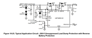
  • Hi William,

    The quiescent current of the device will be same irrespective of common drain or common source topology. 

  • Hi Praveen,
    I do not see how that is possible, because in the common drain topology:
    A, VS, VSNS and C are effectively connected directly to VBATT, regardless of EN/UVLO state

    whereas, in the common Source topology:
    only VS and VSNS are connected to VBATT through a 10k Resistor and A and C are Open circuit

    To me this seems to be a significant difference which should result in a significantly lower quiescent current when it is NOT enabled - ie EN/UVLO=0

  • Hi William,

    As per definition, the quiescent current of the device is the current flowing out of the device GND when the device is enabled.

    The GND current measured when the device is disabled is called shutdown current.

    When enable is pulled low, there would be no current drawn into the A or C pins of the IC. So, The shutdown current will also remain same for both CD and CS configurations. 

    Irrespective of CS or CD configuration, the voltage seen on the VS pin is the same. The 10k Resistor may limit the peak quiescent current (when EN = High) but the average quiescent current remains same with or without the 10k Resistor.

  • Than k you Praveen, that was very helpful