When we use TI's DC-DC TPS54319, we often experience inexplicable burning out of this IC during use, manifested as: the input/output PIN of TPS54319 is short circuited to ground, and the root cause has not been found;
Can you help find TI's engineers to provide a troubleshooting solution? We speculate that it may be parasitic inductance causing input voltage oscillation that exceeds the DC-DC withstand voltage value and causes damage, but we cannot verify it. Please also help confirm with TI's engineers if they have any experience or verification/simulation methods in this area. Thank you!
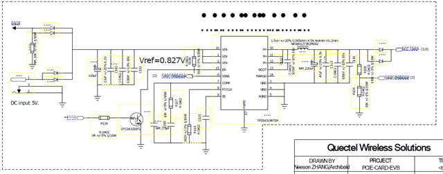
Usage scenario: This EVB is used for the module test board, and TPS54319 supplies power to the module (3.7V) on the EVB, with an input power of 5V adapter. During daily use, TPS54319 occasionally burns out, which occurs quite frequently. Sometimes, when used well, the IC burns out after re powering on, mostly during the EVB power-on stage.
From the monomer analysis of TPS54319, it can be seen that the input/output of the IC is both short circuited to ground. After replacing the IC, it can be used normally;
Please be aware of the above. If there is anything you need to provide, feel free to discuss it at any time. Thank you!
Core demands:Please help me analyze where there are problems and provide suggestions for modifications
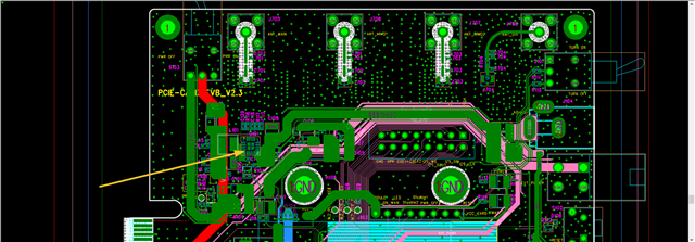
The schematic and layout are as follows: