This thread has been locked.

If you have a related question, please click the "Ask a related question" button in the top right corner. The newly created question will be automatically linked to this question.

BQ79616EVM-021: Wake up problem on BQ79616EVM for onboard J3 UART connector.

Part Number: BQ79616EVM-021
Other Parts Discussed in Thread: LAUNCHXL2-TMS57012, BQ79616

Hello team, 

I'm having a problem just like the one described here. My setup consists on a BQ79616EVM-021 and the launchpad LAUNCHXL2-TMS57012.
When using the EVM's J17 connector with the launchpad, actual cell voltage is printed on CCS and the LED (D1) is on.

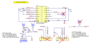
However, changing to J3 connector and following the schematic to communicate correctly (connecting TX, RX, NFAULT and GND), all cell voltages printed are equal to zero, and the LED is off.

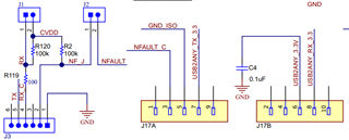
I've tried removing jupers J18 and J21, as Ted said in the linked thread, but it doesn't work. Is it because BQ79616 works with 5V digital level and the launchpad with 3.3V, so I would need to use a level shifter in between?

Please let me know what else should I do to make it work.

Thanks.


  • Hi,

    You shouldn't need an additional level shifter for this to work. The first thing I would recommend checking is the functionality of the digital isolator. Can you probe the inputs/outputs of the ISO7342 (U2 on the schematic). Please also ensure that the isolator has a good connection on each of its pins. Let me know what you find. 

    Best,

    Nancy

  • Hello Nancy, thanks for your reply,

    Yes I could probe the in/out pins of ISO7342, but firstly, if I will be using J3 pins instead of J17, ISO7342 actually would not be used, since its in/out pins are connected only to J17, not J3, am I right? J3's RX and TX pins come directly from BQ79616.
      

    Please let me know if it makes sense to you.

    Thanks.

  • Hi,

    Thanks for pointing that out. Yes, you're correct I misunderstood. What do you observe when probing the TX/RX pins? What about NFAULT?

    Best,

    Nancy