Other Parts Discussed in Thread: TPS1653, TPS2640
Dear TI team,
For the TPS2490 hot swap controller
I have 4 questions
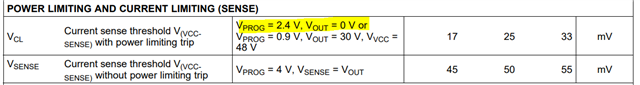
1. In page 6 of theTPS2490 datasheet, there are two spec for "power limiting and current limiting (sense)". One is V(CL) which is said with power limiting and is 25mV.typ. The other is V(sense) which is said without power limiting and is 50mV. So when I use power limiting feature, I should the V(CL) spec of 25mV?
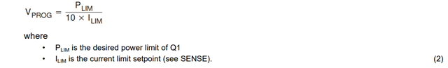
2. When power limit feature is used, PROG pin can be set to 0.4V to 4V through a voltage divider (R3, R4) on Vref. When power limit feature is not used, PROG should be tied to Vref through a 47kohm resistor which is 4V. So when PROG is set to 4V, how do I know whether it is a power limit or not? If I do not know it is a power limit or not, I do not know whether to use V(CL) spec of 25mV or to use V(sense) spec of 50mV for current limit.
3. In the TPS249x_8x_Design_Calculator_REV_B excel sheet. It does not have an option to choose between 25mV and 50mV of V(CL), V(sense) spec in step 2. only one 50mV for current limit calculation which is for without power limit.
4. in the cell F67, comment says compare with min. power limit on cell F46, but cell F46 is current limit. please check.
Best Regards
Sam