This thread has been locked.

If you have a related question, please click the "Ask a related question" button in the top right corner. The newly created question will be automatically linked to this question.

TPS25750: Patch burst download byte sequence

Part Number: TPS25750

I have followed the sequence described in the flowdiagram in the HOST technical manual and have initiated and completed the patch burst download and the download has been acknowlaged. But when i write the PBMc command do i get that the ac indicated data size is 0 and the calculated CRC is 0, and the ac fail code is 0. So I have some questions

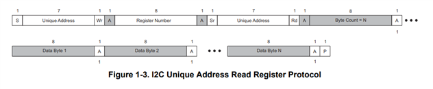
- the readsequence is described as address-register-byte count-data0-data1-...-dataN. But the patch download has no spesified register so should the sequence then be address-byte count-data0-...-datan or should it be address-byte0-...-byteN?

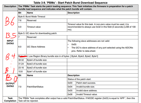
The second question is regarding starting the patch download with the PBMs command, because i figured that I needed to have the address in register 4 and the timeout value in register 5. 
Is it correct that the data bundle size should be in register 0-3 or should it be in register 1-3 as register 0 is also used for outputing data after 4CC commands?

  • Hi Asmund,

    Please follow the powerpoint in the zip file I attached for patch burst mode. The host technical reference manual has some inaccurate information.

    PBMx.zip

    When you are executing the read sequences described in the flow diagram, please make sure you are reading from the TPS25750's 0x09 Data1 register or the 0x08 CMD1 register at the PD controller's I2C address. You should not need to read from the patch download I2C address. In the powerpoint, 0x21 is the I2C address of the PD controller. You will have a separate I2C address for your patch. You will not read from the patch address, so no need to worry about the patch download not having a specified register.

    All reads should follow this sequence: 

    You will not read from the patch I2C address. You will only read from the PD Controller I2C address. The read bit should be set to 1 on the second write of the I2C address (unique address).

    --------------------------------------------------------------------------------------------------------------------------------------------------------

    To answer your second question, I have made changes to the reference manual you are using in the image below.


    Best,

    Alex