This thread has been locked.

If you have a related question, please click the "Ask a related question" button in the top right corner. The newly created question will be automatically linked to this question.

TPS2H000-Q1: Current Sense and Current Limiting Issue

Part Number: TPS2H000-Q1

Hello,

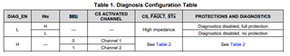
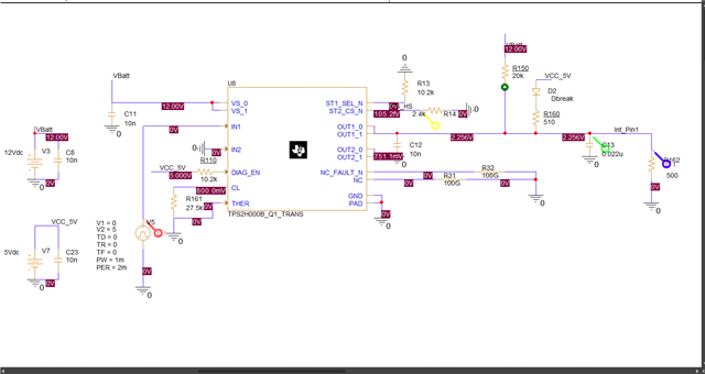
I simulated the TPS2H000BQPWPRQ1 switch on PSpice for TI according to the reference design in the TIDUD43A file. As a result of the simulation, I saw that the current was at 20mA level. However, I could not read the current value from the CS pin. Although the SEL pin is connected to 5V in the reference design, I saw that I could read a voltage value proportional to the current value from the CS pin when I pulled the SEL pin LOW. Is there any harm in pulling the SEL pin LOW to measure the current while using the first channel of the integrated circuit?

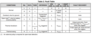
I also want to reduce the current to 10mA instead of 20mA. For this, I replaced the 2.4kR resistor connected to the CL pin with 27.5kR. The current value dropped to 10mA, but this time I started to read a voltage above 4V from the CS pin. Reading a voltage above 4V from the CS pin shows that the integrated circuit is sending an error signal. What do I need to do to set the current to 10mA without error?

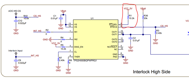
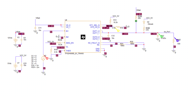
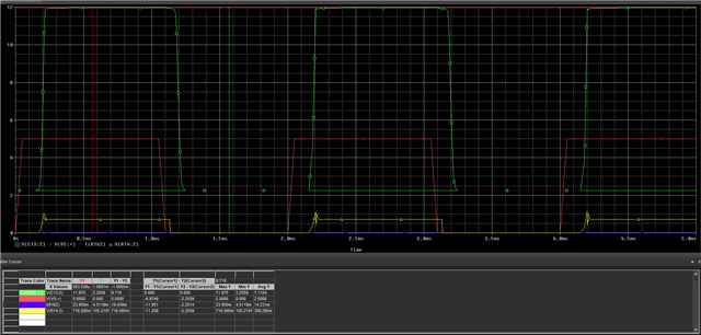
You can see the circuit according to reference design on Sim1.png and Result1.png. There is no CS signal.

Sim1Result1

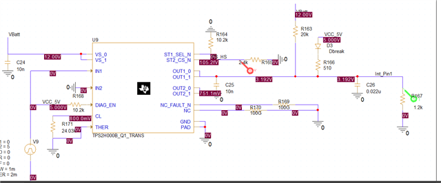
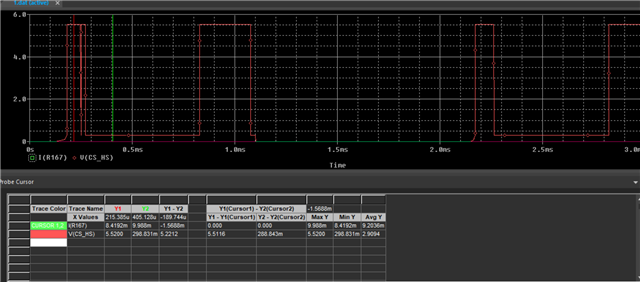
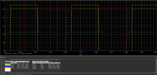
The CS signal is correct and current is 20mA on Sim2.png and Result2.png after I pulled SEL pin to low.

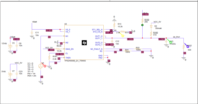
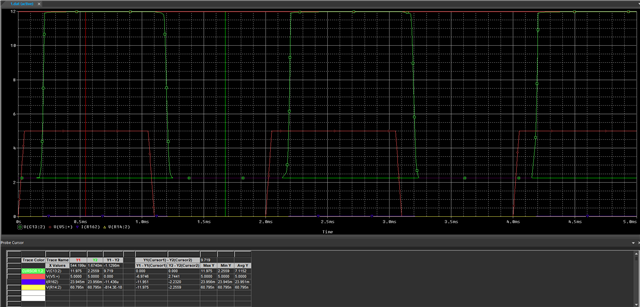
The current is 10mA but CS pin shows fault on Sim3.png and Result3.png after I changed CL resistor value to 27.kR from 2.4kR

Thank you for your help.

Sincerely,

  • Hi Ismail,

    Is there any harm in pulling the SEL pin LOW to measure the current while using the first channel of the integrated circuit?

    As shown in the table below, the SEL pin has to be LOW in order for the CS pin to read Channel 1. Otherwise you'll be reading from Channel 2.

    Reading a voltage above 4V from the CS pin shows that the integrated circuit is sending an error signal. What do I need to do to set the current to 10mA without error?

    The reason the CS pin is sending an error signal is because the device is actively current limiting. As you can see in the table below, when the device experiences overload condition it shows a fault in the CS pin. When providing 12 V, the 500 Ω will always try to pull about 24 mA. Therefore, with a 10 mA current limit the device will essentially always be current limiting.

    Best Regards,

    Gabriel

  • Thanks for your detailed answer. I got confused about SEL pin configuration because of reference design on TIDUD43A.

    I got it now. In my circuit, SEL pin goes to low. No problem.

    About current limit and sense function, I simulated the circuit again with different load resistances, I saw the difference.

    As a result, I will connect CL pin to ground with 24,03kR to limit current to 10mA. If the load resistance is less than 1.2kR, the current goes to above to 10mA then the TPS2H000 will limit to curret to 10mA (@12V batt voltage). And I will see more than 5V on CS pin as an error message.

    If the load resistance is more than 1.2kR, the current will be less than 10mA, I will see the current signal on CS pin without error message.

    I think I got it clearly. But there is still a problem on my circuit. As you can see my bat voltage is 12V, Rload is 1.2kR. So the current should be 10mA. The CL resistor is 24.03kR so current limited to 10mA. Why do I see some short error voltage signals on the CS pin? If I reach the limit, the CS voltage signal should be more than 5V always, but the CS voltage is not stable. Is there any idea about the reason ? Might be the surge current of capacitors? 

  • Hi Ismail,

    Because you're setting both the current limit and load current (using 1.2 kR load) to 10 mA, any slight variation in current can trigger current limiting. This can be resolved by slightly raising the current limit values. I would recommend lowering the CL resistance (therefore increasing current limit) to a value that's acceptable to your application to solve this issue.

    Best Regards,

    Gabriel

  • Thank you for your interest.

    I want my circuit to limit the current 10mA but be sensitive enough to measure the current if current falls below 10mA. So 24.03kR is the limit. Everything perfect now.

    Best regards.