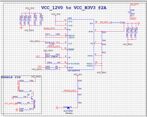
I am using LM61480 to generate -3.3V from 12V of load current 4A. Inductor part Number - IHLP2525CZER2R2MA1. Kindly find the attached Schematic for review
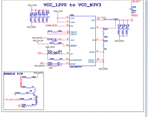
I am using LM61480 to generate -3.3V from 12V of load current 4A. Inductor part Number - IHLP2525CZER2R2MA1. Kindly find the attached Schematic for review