This thread has been locked.

If you have a related question, please click the "Ask a related question" button in the top right corner. The newly created question will be automatically linked to this question.

TUSB1046EVM: DP Output not working on EVM

Part Number: TUSB1046EVM
Other Parts Discussed in Thread: TPS65982, TUSB1046-DCI, TPS65987D

Could you help me understand the TUSB1046EVM video output operation?

I have a DisplayPort cable and a USB3 cable connected from a PC to the inputs of the EVM. When I connect a USB-C device to the EVM, I get full rate USB data pass-through as expected. I can even flip the USB-C cable without issue.

However, when I connect a USBC-to-DP cable from the output of the EVM to a monitor, I am not getting any video output, with the cable flipped in either orientation. To troubleshoot, I used a VGA output on my PC to connect a second monitor and see if Windows was detecting the USB-C/DP monitor. I observed then when I plug/unplug the USB-C cable Windows does detect something, but it said the monitor was not active and would not output video to it.

I did also try to set the jumpers into a mode to force DP output. I set I2CEN low to place in GPIO mode. Then I used the jumpers to set CTRL1 high, CTRL0 low, and FLIP high/low to force 4 Lane DP mode, but this did not seem to work. As a side note, I also set them all low to put the device in power down mode, and this didn't seem to have any affect (as I was still able to connect USBC devices). So I'm a but confused on how these pins are supposed to work. 

Any suggestions on why I cannot video output from the USB-C port on this EVM?

  • Hi Kevin,

    Based on the description, it sounds like there may be an issue with using the USB-to-DP cable or possibly the monitor.  These are the differences between the passing/failing tests.

    Can you send me a link to the USB-to-DP cable, so I can take a look?

    Regards,

    Nicholaus

  • Hi Nicholaus,

    I've actually tried several cables: USB-to-DP, USB-to-HDMI, USB-to-DVI. I tested them all on a laptop with a USB-C port and they all output video as expected. They only seem to not work with the TUSB1046EVM. I also know the DP output and cable from the PC is good because I hooked it straight into the monitor as a test.

    Thanks,

    Kevin

  • Hi Kevin,

    Thanks for confirming that.  The fact remains that we get different results from the EVM with USB-C cable and the USB-to-DP cable.  Can you send me the link to the cable I can take a look?  I might be able to reproduce the issue in our lab.

    Regards,

    Nicholaus

  • Nicholaus,

    No problem. I have used all of these cables below in my testing. But as mentioned, they all work fine when connected to a USB-C port on a laptop so I'm doubtful it is a cable issue in my TUSB1046EVM testing. It seems like the mux just isn't switch the lanes properly. 

    USB-C to DVI:
    www.amazon.com/.../ref=ewc_pr_img_4

    USB-C to DP:
    www.amazon.com/.../ref=ox_sc_act_title_1

    USB-C to HDMI:
    www.amazon.com/.../ref=ewc_pr_img_1

    I'm also attaching a screen shot from the PC when I connect the USB-C to DP cable to the TUSB1046EVM. The PC recognizes the new monitor ("SyncMaster" is this case) but it shows it is inactive. The other monitor (Dell) is the one I have connected directly to the PC via VGA. I'm not sure what would cause the SyncMaster to show up but be inactive. 

    And just to provide more info, the board number is INT053 Rev B, as shown. Can you confirm what jumpers should be installed?

    Thanks again,
    Kevin

  • Hi Kevin,

    Thank you.  I'm sure they work well.  The links are only so that I can check to see what is in the cable.  Unfortunately, the vendor doesn't give any information about that.  I will look for a similar cable in the lab to test with and let you know the results.

    Regards,

    Nicholaus

  • I also found a monitor that has a direct USB-C input and so I used a USB-C to USB-C cable to connect EVM to monitor. But I get a similar result - Windows thinks the monitor is there but no video data is provided. 

    Is it worth trying to reprogram the TPS65982 using the GUI?

  • Hi Kevin,

    Thanks for that test.  Section 7.4.1-7.4.3 of the datasheet:

    "After power-up (VCC from 0 V to 3.3 V), the TUSB1046-DCI defaults to USB3.1 mode. The USB PD controller upon detecting no device attached to Type-C port or USB3.1 operation not required by attached device must take TUSB1046-DCI out of USB3.1 mode by transitioning the CTL0 pin from L to H and back to L."

    Was this step performed first?

    Regards,

    Nicholaus

  • The TPS65982 on the EVM should be controlling this correct? I am not manually setting these pins.

    I did scope the CTL0 and CTL1 pins and they do correctly transition based on the device connected:

    When I plug in a USB3.1 device: CTL0 goes H, CTL1 goes L

    When I plug in a monitor (thought a USBC-to-DP adapter): CTL0 goes L, CTL1 goes H

    When I plug in a monitor (direct USB-C connection): CTL0 goes H, CTL1 goes H. I assume they both go high because the monitor has a built-in USB hub as well.

    So the TPS65982 seems to be toggling the GPIO pins correctly to the 1046A, but I'm not getting any video when connecting a DP device. 

  • Hi Kevin,

    Yes, the PD controller should be doing this, but the toggling of CTL0 must happen before attaching the DP devices to take the TUSB1046 out of USB mode.

    "...device must take TUSB1046-DCI out of USB3.1 mode by transitioning the CTL0 pin from L to H and back to L."

    According to your summary.  Powerup -> CTL0 at H -> CTL0 goes L -> CTL0 goes H.  So, it's possible that the device is still in USB mode.

    Try toggling the CTL0 pin (L, H, L) after the TUS1046 has power, before attaching the first USB3.1 device and see if this resolves the issue.  I will check this in the lab as soon as I can.

    Regards,

    Nicholaus

  • I tried the steps you outlined, moving the jumper on CTL0 from L, H, L after power on. Then I connected the USB-C cable for the monitor, but I still get no signal. 

    I just did a continuity test and noticed something odd:

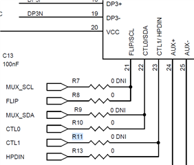
    • CTL0 HDR (J2) to TUSB1046 Pin 22 - Good
    • FLIP HDR (J3) to TUSB1046 Pin 21 - Good
    • CTL1 HDR (J1) to TUSB1046 Pin 23 - OPEN

    So it doesn't look like the GPIO signal from the TPS65982 for CTL1 is actually being received by the TUSB1046A.

    Can you provide me with the schematic for the board I have (INT053 REV B)? The EVM manual shows a different rev. Is there a resistor that might be DNI'ed that I need to install?

    Thanks

  • Hi Kevin,

    Sorry for the delay, I'm having some difficulty finding that schematic; however, I can say that the resistor number on the one I am looking at is R163.  Is that populated?

    Regards,

    Nicholaus

  • Without a schematic or board file, I used a meter and tried to trace the path from TPS65982 to TUSB1046A. It looks like the signal goes to the jumper, then goes to R11 which is on the bottom of the board, then to the TUSB1046A. On my board, R11 is unpopulated, which is why I would assume CTL1 is not getting to the TUSB1046A. When you find the design files for the REV B board, could you confirm this is the case. I would also assume this is a 0 ohm resistor.

  • Hi Kevin,

    Will do.  I'm reaching out the engineer that designed the EVM now to understand the revision history.

    Regards,

    Nicholaus

  • Hi Kevin,

    Sure enough,  R11 is missing in Rev B.

    Regards,

    Nicholaus

  • I assume that's a mistake then and R11 should be installed and R13 DNI?

    I just swapped the resistor on my board, but alas, still not display output. 

    Could you send me the full schematic for the REV B board? Thanks

  • Hi Kevin,

    Did you order this EVM from ti.com?  I don't believe this revision is the active one.   Unfortunately, I am sick right now and am unable to go into the lab, but as soon as I can I will go look to see if we have any Rev B boards to test.... I don't believe we do.

    Here is the schematic.  It is named Rev D in the files, but it was checked and seems to match the Rev B design.

    INT053D-001_SCHEMATIC.pdf

    Regards,

    Nicholaus

  • Thanks, the schematic you sent does seems to match the board I have. It does raise some other questions though:

    For one, a TI rep once sent me a board file titled "INT053C_PCB.brd" however the silkscreen layer shows "REV_B". But if it were Rev B, it doesn't match the actual Rev B board I have. It seems every company struggles with config management!

    The schematic you provided shows U6 part TPS65987D, however it shows a 48-pin package (which does match what I see on the board). However the datasheet for TPS65987D only indicates a 56 pin package. Does the EVM just have an older, EOL package type?

    Looking at U6 under a scope, the marking actually seems to indicate it might be 65988 - unless I'm misreading the markings. Could you confirm?

    Hope you feel better!

  • Hi Kevin,

    Thanks!  I'm wondering if this board was something we used internally, but we didn't expect to release on ti.com and this is the reason for the lack of documentation.  It just so happens the TI rep had one and sent it to you.  

    I am following up on this to see if that is in fact the case.  

    Regards,

    Nicholaus

  • Hi Kevin,

    I was able to confirm that this board was never released.  It was an early version of the board, which is why you see a prototype PTPS659 part (denoted with a "P") on the board.  The TPS659x was likely not released at the time this board was created either, and the group that produced it may have made changes to the design before release.  That's why you see differences in the documentation.

    Regards,

    Nicholaus

  • Oh wow. Thanks for digging around and finding this out.

    Is there any way I can return it and get it swapped out for a newer, official release version?

  • You may need to purchase the EVM on ti.com: TUSB1046EVM Evaluation board | TI.com

    I would recommend you reach out and contact your TI rep to see if anything outside of that can be done.  

    Regards,

    Nicholaus