Because of the Thanksgiving holiday in the U.S., TI E2E™ design support forum responses may be delayed from November 25 through December 2. Thank you for your patience.

This thread has been locked.

If you have a related question, please click the "Ask a related question" button in the top right corner. The newly created question will be automatically linked to this question.

TPS61033EVM: TPS61033EVM-105 does not perform as excepted

Part Number: TPS61033EVM
Other Parts Discussed in Thread: TPS61033

we have this dev kit.

Test 1.

The input voltage is 3V/2Amp

Output voltage is set to 5V.

Test 2. 

The input voltage is 4V/2Amp

Output voltage is set to 5V.

we are running a bench test. as soon we increase the load which consumes 300mA, the voltage output drop below input voltage.

Mode is set to Ground.

Also according to TPS61033 datasheet the input voltage range is 1.8V to 5.5V then why dos the EVM stats its input range is 3.6V to 5.5V ?

any insight ?

  • input voltage is 3.7V/2Amp

    Output load is consuming around 400mA at this point.

    I would expect it to hold study at 5V.

  • Hi Gama,

    I run a few tests under 3.7V/2A input and 4V/2A input and I didn't meet your problem. So I would like to know more details about your test.

    1.Did you adjusted any components on the EVM board

    2.Did you start up at 2A input or you started up with a lighter load and added loads after the output reached 5V.

    3. How is the current waveform of IL and voltage waveform on SW pin(both at 500us/div time scale).

    4.How did you set up your input DC source? Is it working in CV mode? What is the set current limit of that source.

    5.How did you set up your output load?Is it working in CC mode or CR mode? What is the set current limit of that load.

    And about the EVM input range issue, the EVM input voltage range is also 1.8V to 5.5V. The EVM user guide only listed its typical input voltage as 3.6V and the webpage of that EVM stated its input range as1.8V-5.5V. So I would like to know where did you find that information of input range 3.6-5.5V so that I can modify that wrong information.

    Best Regards,

    Travis

  • 1. Using the dev kit as it is

    2. input is constant from beginning and load is a motor driver. I tested with pure resistive load as well. Both yielded similar results 

    4. I used batteries and bench power supplies 

    5. its a motor

    The input voltage is listed on Digikey and mouser.

    thanks

  • Hi,

    Since the device works well on my bench, I would like to know some working waveforms on your bench:

    1. Output current of that motor driver/resistive load

    2. Input voltage of that battery or bench power supply

    3. Input current of that EVM

    4.Voltage between TP1 and GND

    (All at 500us/div)

    Also, I would like to know the resistance of that resistive load.

    Best Regards,

    Travis

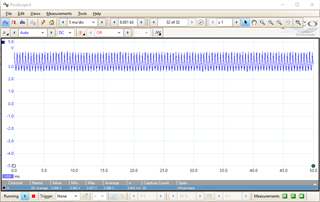
  • 1. 5V/750mA

    2&3. 2.9V/3Amp

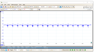
    4.


  • Hi Gama,

    It seems that the bandwidth of your testing device is seriously inadequate and the working waveform is far from expected. Can you provide the brand and model of your power supply and load motor so that I can search for their datasheet.

    Best Regards,

    Travis

  • I tested with two power supplies. 
    1. two AA batteries in series. 

    2. BK precision bench power supply.

    The load is a generic 5V DC geared motor.

  • Hi Gama,

    I can't find the datasheet without Specific model of the BK supply and the motor.

    Best Regards,

    Travis

  • Hi Gama,

    Maybe your chip has suffered some damage. Try measuring the diode from Vout to SW and from SW to GND. Check if the diode can block and conduct normally.

    Best Regards,

    Travis