This thread has been locked.

If you have a related question, please click the "Ask a related question" button in the top right corner. The newly created question will be automatically linked to this question.

UC2827-2: INITIAL POWER ON CONDITION, BUCK PIN GENERATING THE PWM

Part Number: UC2827-2

Hi,

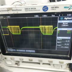
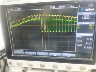
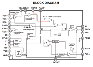
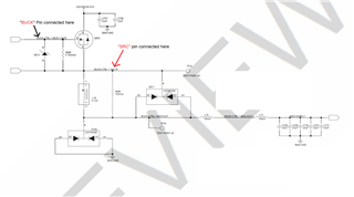
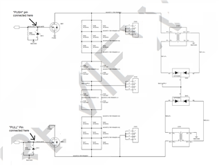
We are using UC2827DW-2 in our design for 200W Power Supply controlling. At initial Power ON time, Buck Pin generating the PWM frequency with Soft Start disabled condition (At no load condition).

So our buck converter goes to the Power Shut down mode.

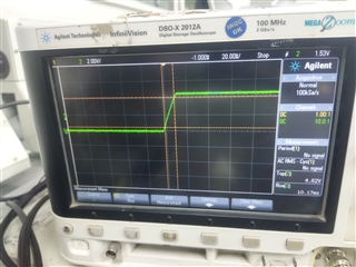
If the Soft Start Pin enabled, Buck pin and  SRC Pin goes to the 9.7V.

What will be the output of Buck and SRC Pin at Soft start enabled/disabled condition.

  • Hi,

    Please refer to its datasheet block diagram to help understanding. In typical connection from the two error amplifiers, when soft start enabled the Buck to SRC will output drive pulses to the high side MOSFET gate to source, until the feedback loop takes control. When disable soft start Buck to SRC will be low to turn off the high side MOSFET in the buck regulator.

  • Thanks for your Reply.

    You above given statement actually expected.  But in Soft Start disabled condition itself Buck Pin drive output pulses.

    I have attached the wave form probed at Buck & SRC Pins (Both soft start enabled and disabled conditions).

    Soft start disabled condition, potential difference bw the buck and SRC pin is 9.7V , so the MOSFET driving without given any reference voltage.

    Shall we kept floating the Current Sense Amplifier Positive pin to resolve this issue ? . Please provide your feedback.

    Wave Form Probed at Buck and SRC Pins

    Yellow color is BUCK

    Green color is SRC

  • Hi,

    Please also provide soft start pin waveform in your waveforms.

    Also please provide your circuit for review.

  • Hi Hong Huang,

    Please find the attached Soft Start Wave form and Buck Controller IC circuit for your reference.

  • Hi,

    please provide soft start, buck and SRC in the same picture so we can see their relationship.

  • Hi,

    where are buck and SRC connected to? please show their connections to the power stage.

  • Hello Hong,

    The requested details will be shared shortly.

    We are currently in the process of analyzing the debugging of the UC2827.

    During this analysis, we shorted the SS-pin to ground. Despite this, we observed the same issue as mentioned earlier.

    We would like to determine whether, in any situation, the buck operation will continue if the SS-pin is shorted to Gnd.

  • Hi,

    When short SS to GND, buck should not have pulses in any time, but you see SS only disable pin 10. If pin 10 open, then SS cannot achieve its soft start function, or stop pulses. Your circuit does not show clearly where pin 10 is connected so please also provide this connection. I think it is better you provide the complete circuit of these pin connections and the power stage in order to help resolve or answer your questions.

    We need to see the waveform of SS, buck, and SRC, and where buck and SRC connected to the power stage.

  • Hi,

    Please find the attached Wave forms of Buck and SRC pins at SS-pin shorted to GND. It is observed as difference bw the Buck and SRC voltage is around 8V.

    10th Pin is not open. It is connected to the Voltage Compensation Loop (Exactly it is connection with C755 in this circuit). 

    Yellow - SRC, Green - Buck .

    Zoomed Image for reference. 

  • Hi,

    Can you provide pin 10 connections with zoomed in on what you described to volage compensation loop? Please provide your full circuit of this device and your power stage connections. 

    Also where is the SS waveform in your picture.

    I strongly suggest you to provide a full circuit with the IC and the power stage as it is not clear to me how your SS, buck and SRC connected in your application. So very difficult to make analysis or understand the behavior.

  • Hi,

    What is IC pin 6 voltage when SS short to GND? Pin 6 (CEAO) should be zero when SS short to GND. When Pin 6 is zero, there will be no pulses based on the ds diagram.

  • Hi,

    I have attached the SRC, BUCK and SS Pin connection. We are following the Simple Voltage Control Mode. VEAO (6th Pin) and CEAO (10th Pin) Shorted by 0-Ohms resistor shown in circuit.

    we will share the CEAO wave form at the time of SS-pin shorted condition.

  • Hi Huang,

    CEAO pin voltage observed 4V at SS-pin shorted to GND condition.

    Note : VEAO (6th Pin) and CEAO (10th Pin) Shorted in circuit

    .

  • Hi,

    SS short to GND can only disable pin 10. To disable pulses pin 6 needs to be disabled but now it stays 4V. It looks pin 6 not pulled down by pin 10 due to pin 12 forced pin 6 high.

    I think you need to rearrange pin 12 connections so pin 10 to connect pin 12 in a way to force pin 12 low when pin 10 low so to force pin 6 low then to disable pulses.

  • Hi,

    VEA+ (14th Pin) and CEA+ (12th Pin) already Pull down to GND with 1k Ohm resistors.

  • Hi,

    can you check pin 6 which needs to be low to disable the pulses based on the datasheet diagram?

  • Hi,

    As no communication for a few days, I assume the issue is resolved. I will close this thread. if you need further support you can reopen this thread or create a new one.