Because of the holidays, TI E2E™ design support forum responses will be delayed from Dec. 25 through Jan. 2. Thank you for your patience.

This thread has been locked.

If you have a related question, please click the "Ask a related question" button in the top right corner. The newly created question will be automatically linked to this question.

ISO5852S: output clamped to VEE2

Part Number: ISO5852S

I'm testing the ISO5852S driver to replace the equivalent NCD57000 (onsemi) in a 6kw IGBT buck converter, with a frequency switching of 40kHz.

When i apply the pwm signal to the input, the output always stays at VEE2. 

I state that with NCD57000 (pin-out compatible) I don't have this problem (same board, same conditions)

I summarize the tests I have carried out.

1) I installed the ISO5852S driver in a "virgin" pcb board and applied a pwm with the oscilloscope signal generator. in this case I have no problems.

2) I installed the component in the pcb board also populated with other components (microcontroller, logic gates, etc..). If I apply a signal to the driver input, the output always remains at -5V (VEE2) and there is no switching, even though the input signal is correct.
NOTE: if I install NCD57000 in this same pcb board, this works correctly.

Since things "do not add up" I proceeded by doing these three tests:
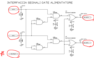
1) Disconnected microcontroller output and connected signal generator in place of the microcontroller output (outl schematic point), in doing so the driver does not work.
2) Microcontroller output connected directly to driver input bypassing the logic gates, doing so does not work.
3) Removed the NOR logic gate and directly connected the signal generator (point DRV OUTL schematic) to the driver input, this to put me in conditions similar to the test ones on the "virgin" pcb board. By doing this, the driver works correctly.

I really can't explain this phenomenon, as in all cases I measure the IN+, IN-, FLT, RDY, RST signal of the driver correctly.

It seems to be a problem due to the type of source that generates the pwm and/or the presence of components between the source and the driver input. Could it be a problem related to the current that the source that generates the pwm can deliver?

  • Hi Francesco,

    Thanks for reaching out. Can you please provide the below information:

    1. IN+ & IN- voltage at the driver pins and not the MCU output.

    2. FLT & RDY pin status or waveform.

    3. Voltage at the DESAT pin and making sure the DESAT pin is connected to the IGBT power module.

    4. Making sure all the pins are soldered properly on the board and measuring the voltage at each pin to make sure there is no short on the board.

    5. Making sure the components between microcontroller and the input are properly connected.

    Can you please specify what the below signals are:

    It would also be good to check the status of the OC_FAULT pin as it it goes high the OUTH & OUTL both goes low.

    Let me know if any of this works. We're here to de-bug and help solve the issue.

    Best,

    Pratik

  • Dear Patrick,

    thank you for your reply. I report the requested information point by point:

    1) IN+ is pwm signal at 3.3V, IN- is connected to gnd, attached photo of signals

    2) FLT is at 3.3V, RDY is at 3.3V, RESET is at gnd, attached photo of signals

    3) Desat is connected to igbt power module, attached photo of signals

    4) Checked and checked, i try also other IC driver to verify that the problem does not come from a single integrated circuit

    5) See point 4


    OUTH, OUTL are the outputs of MCU that generate the PWM

    Drv_OUTL, Drv_OUTH are the input of drivers (IN+)

    OC_FAULT is a signal that lock the PWM in case of overcurrent situation, instantly lock the pwm signal from the micro to the driver.

    C1 FAULT, C3 IN+, C4 VGS

    C1 READY, C3 IN+, C4 VGS

    C1 RESET, C3 IN+, C4 VGS

    C1 DESAT, C3 IN+, C4 VGS

  • Hi Francesco,

    Thanks for the follow up. In the waveform RST signal is LOW, but for the driver to work the RST signal needs to be HIGH. 

    Please let me know if this works.

    Best,

    Pratik.

  • There was an error on the reset pin, I always made the comparison with NCD57000. the latter seems unaffected by the fact that the reset is low, while ISO5852S actually keeps the internal logic disabled in case the reset is low.

    thak you so much.

  • No problem! Happy to help!

    Best,

    Pratik