This thread has been locked.

If you have a related question, please click the "Ask a related question" button in the top right corner. The newly created question will be automatically linked to this question.

TPS568231: choosing optimal output capacitor

Part Number: TPS568231
Other Parts Discussed in Thread: TPS56C231

Hello Team, 

my customer asks the following:

I plan to use the TPS568231 (alternatively possibly the TPS56c231) in a new design.

The requirement is: voltage conversion from 12V to 3.3V at an output current of max. 8A.


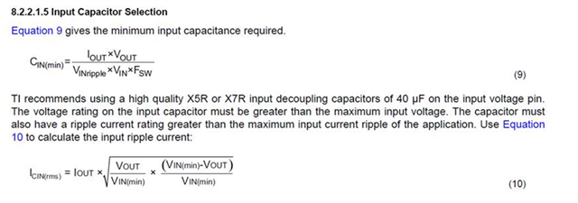
The datasheet talks on page 15 about the double pole of the output LC filter, which must not be too far from the zero of the ripple injection.
I think I need about 150uF - 250uF capacitance at the output of the switching regulator to catch transients.

Now my question:
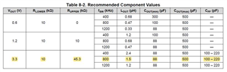
Can I assume that the switching regulator will operate stably if I stay within the values in the table on page 21 in the datasheet?
I would choose the yellow highlighted configuration. C_out will stay well below 500uF in any case.

thanks 

Jan

  • Hi Jan,

    Yes, if you choose the yellow highlighted configuration, the system would be stable. 

    Thanks,

    Nancy

  • Hello Nancy, 

    thanks for the reply. But the given range is very big 88-500uF. Is there a way to determine the optimal cap size. Have you done simulations for that?

    Thanks 

    Jan

  • Hi Jan,

    The way to determine the optimal cap size is customer application. Consider the following when optimizing the value of output capacitor.

    1. The output voltage ripple. 2. The output voltage deviation during the load transient.

    As long as customer follows table 8-2 with recommended component values, the system would be stable. The designer already did the simulation and that is why we listed them in the datasheet.

    Thanks,

    Nancy

  • Hi Nancy,

    My customer likes to ask another question concerning the TPS568231:


    Is the capacitance of 40uF required on EACH input pin of the TPS568231, or is a TOTAL input capacitance of 40uF required?
    Looking at the layout example I suspect that 40uF is required on each input pin. That means 80uF minimum input capacitance in total.


    I´m not sure if I understand equation (9) correctly, but the lower the input ripple voltage is the more minimum input capacitance is needed?


     Thanks Jan 


  • Hi Jan,

    Yes, your understanding is correct. the lower input ripple required more minimum input capacitance. We recommend 40uF input cap for each input pin and total 80uF. 

    Thanks,

    Nancy