This thread has been locked.

If you have a related question, please click the "Ask a related question" button in the top right corner. The newly created question will be automatically linked to this question.

TPS92515HVEVM-749: PWM dimming couldn't be done.

Part Number: TPS92515HVEVM-749
Other Parts Discussed in Thread: TPS92515

Hai,

I have been using the Eval board for 2 LED in series (24V)

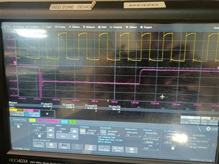
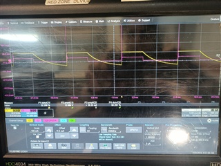
the LED is turned on with the voltage at J3, but the dimming is not happening by giving PWM at the pin

we tried different combinations of frequency, duty cycle, etc, the PWM peak was given between 3.3 to 5

The R14 was removed for the dimming operation.

we tried all possible scenarios, but we couldn't dim the LEDs with the Eval board, tried with another board also but the same results,

hope you can help me with this issue ASAP

thanks in advance,

regards

Rohini

  • Hi, Rohini, 

    Could you share the waveform you captured during the test? Especially SW and PWM pins? thanks.  

  • PWM and SW  Current wave forms

    SW wave form

    please look into it and help in resolving the issue

    thanks in advance 

    regards 

    Rohini R

  • Rohini, 

    Some questions: 

    1. Is there any change on board you have done? What is input, output voltage and current? 

    2. For figure 1, per my understand, ch1 is PWM control signal, is it correct? Please keep low level voltage well below 0.8V for test again.  

    3. For figure 1. can you share me details about ch2? how do you measure CH2? What  current it measures? 

    4. For figure 2.  what are Ch1 and ch2 respectively presented? 

  • Hai

    Please find the answers below,

    1. No changes have been done other than removing R14, Input voltage is 18V, current 0.8A  , 2 LEDS in series given through J3,

    2. Yes, ch1 is PWM control, we have kept the peak from 2.5 - 5 V as per data sheet, next time will keep below 0.8V

    3. CH2 measures the current through J2 LED+

    4. Ch1 is the SW LED+ Voltage and Ch2 is the LED current in the same pin.

  • In item 1, can you confirm 2 LEDs in series given through J3, not J2? 

    In item 3, It shows that LED current is on/off, which means VLED+ changes with some kind of control; The LED current you measured is not 2A, just around 100mA. While according to 18V 0.8A input with assuming 7V output, it seems output current can be 2A. I guess there is error for current testing. 

    In item 4, What do you mean SW LED+ voltage? SW is PIN 5 of TPS92515, LED+ is at J2 PIN, they are different. 

    Also, LED current and SW current are different as there is 2.2uF output capacitor at J2. 


    If C1 in fig2 is LED+ voltage, it shows that LED is on/off switching. 

  • Hai , Thank you for the reply, i was able to do the LED dimming using a 1Khz PWM from a external function generator,

    Right now we are using a PIC controller to generate IKhz PWM , but the LED is blinking and not dimming.