This thread has been locked.

If you have a related question, please click the "Ask a related question" button in the top right corner. The newly created question will be automatically linked to this question.

LMR54406: FRA while working in the current limit mode.

Part Number: LMR54406


Hello!

Introdution
I have a buck converter which have to charge battery so it works in current limit mode.
Instead of using internal current limiting feature I use external ciruit which consist of:
1) differential amplifier which is sensing output current (voltage drop on 1R resistor)
2) ouput of this diff-op is connected to a voltage divider with a NPN transistor
3) if the current reach certain limit the NPN transistor inject voltage to the feedback network of the converter which decrease output voltage.

I attach a .zip file with a LTSpice simulation of the circuit.

HW_Limiter.zip

Problem
The customer wants to be 100% sure that this system is stable under all conditions,
and in particular that there will be no audible frequency oscillation (since there is a loudspeaker in the system).

Solution
Typically a FRA is performed to check gain and phase margin.
But in this case converter works under special conditions and it can be seen on the pictures below.
These photos refer to the AP64060 tests, but the LMR54406 has the same pinout and similar capabilities.

Bode Plot of the DUT which works under normal conditions e.i. Constant Voltage (CV) mode.

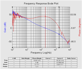
Bode Plot of the DUT which works under current limit conditions e.i. Constant Current (CC) mode.

I use 10 ohm resistors in series with the feedback and the 1:1 1Hz to 100kHz injection transformer is used.

Question

Is FRA an appropriate method to check the stability of such a system.
How to interpret the results.
What would the results be if there was a possibility of being unstable and generating audible noise.

  • HI

    As we don't have allow to install LTspice, can you share the simulation schematic and how you test the FRA in CC model? 

    Can you share the CV bode plot test condition and schematic, we can check whether LMR54406 have similar bode plot in this condition. 

    if LMR54460 have similar CV bode plot with AP part, then it will have similar CC bode plot with AP part.

    Thanks

  • The AP64060 circuit:
    Supply Voltage 24V || Output Voltage 16V || Inductor 47uH || Output Capacitors 3x 4,7u 
    Load = 47Ohm ≈ 330mA (load sees smaller voltage because of drop on 1Ohm resistor and on the protection diode)
    FRA Setup:
    100Hz to 1MHz 100 Steps/Decade || Probes AC coupled || Attenuation 1X

    There are a lot of other parameters but it's not a point.
    Sorry but I wasn't clear.
    The most important thing to me is:
    FRA should be performed in Continous Current Mode (CCM) of the converter (injected signal should not cause DCM or reaching limits of PWM switch)
    When I test device while operating in CV I get bode plot which looks normal. I know how to interpret the results. Phase margin is 72° so converter is stable.
    That's easy part - every tutorial explain that.
    But I not sure how to interpret bode plot when converter works in CC mode. We have two phase margins (gain goes through 0dB two times). I would like to know how to judge if my ciruit will be stable or not in this CC mode or it is not a way to go.