This thread has been locked.

If you have a related question, please click the "Ask a related question" button in the top right corner. The newly created question will be automatically linked to this question.

TPS552882: Parallel Operation

Part Number: TPS552882
Other Parts Discussed in Thread: TPS55288

Hello TI Team,

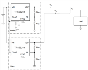
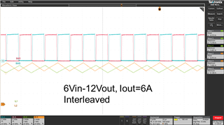
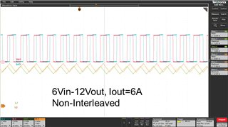
I would like to know if this device can operate in parallel as well. The battery charging IC on my device is not capable of handling more cells and I am looking to increase battery capacity and power using two devices in parallel for certain applications. The output from a single converter needs to be capable of 12V-6A.

Thank you,

Matthew

  • Hi Mattew,

    May I know what is the input voltage range of the input battery? Also, what is the application here, do you have any blocks to explain that? Thanks.

    BRs,

    Bryce

  • Hi Bryce,

    The voltage range from the battery is 6V-16.6V. I am designing a UPS that can use 2-4 LiPo cells in series depending on which device it powers. 

    Matthew

  • Hi Matthew,

    The single TPS55288 can output 12Vout/6A with 6Vin, but the thermal would be a concern if it works for a long time. Would the LiPo cells outputs 72W when the single battery voltage is only 3V?

    We have not tried with two TPS55288 in parallel on bench, but from theoretically, it is possible to do that. We can try with that, if you would like to know.

    BRs,

    Bryce

  • It would be great if you can try it and let me know the best configuration. The battery needs to provide up to 72W until the cells reach 3V. 

    Matthew

  • Hi Matthew,

    Yes, I can connect the two EVM in parallel with the external setup, but this will take some time due to bandwidth limit, it may take 1-2 weeks, I will reply to you here when I get some results.

    BRs,

    Bryce

  • Hi Matthew,

    Sorry for late reply, our bandwidth is very limited recently. According to my bench test, when these two boards are connected in parallel, each board would take some loading current but the power sharing can't be realized since there is no external loop to regulate this.

    Below is the test schematic and test waveforms under interleaved and non-interleaved, 6Vin-12Vout/6A.

    External connection:

    1.Vin, Vout, GND are connected.

    2.FB pin: separate resistor divider.

    3.COMP pin: use single compensation network and connect together.

    4.SYNC pin: can use external PWM signals(phase shift 180°) for interleave operation.

    BRs,

    Bryce