Hi ThereREF Design POE.pdf
Pls specify what parts consist of the flyback DC-DC in the reference design as attached file of POE.
BRs
Peter Hsiao
This thread has been locked.
If you have a related question, please click the "Ask a related question" button in the top right corner. The newly created question will be automatically linked to this question.
Hi ThereREF Design POE.pdf
Pls specify what parts consist of the flyback DC-DC in the reference design as attached file of POE.
BRs
Peter Hsiao
Hi Peter,
I'm sorry, I'm not sure I understand your question, can you clarify what you are asking for?
From looking at the file, the design looks more like a forward topology, not a flyback.
You could look at TIDA-050023 for an example of using TPS2373 with flyback design.
If you are wanting flyback design, you would need to change the following:
VCC Input: ACF vs Flyback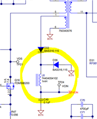
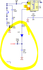
Add clamp to primary side: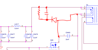
Secondary side should be either diode or mosfet for synchronous flyback.
Currently you have the secondary side set up for active clamp forward.
Example of Output Diode: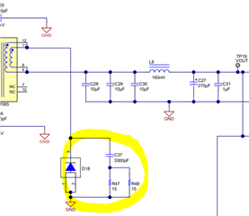
For the transformer T2, can you please send datasheet? To see if this is made for ACF or flyback?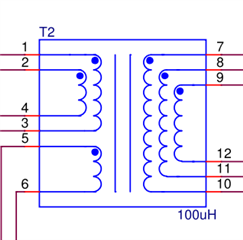
Again, it may be easier to refer to TI's reference design, TIDA-050023
Thank you,
Sarah Lao
Hi Sarah
Sorry, I thought it was flyback, thanks for your clarification, so pls provide me the design guide and training for ACF. so that I can debug for some boards with failure of not power on issue. such as if C7 in my attached schematic has no output of 12V, what is the steps to find out the rootcause, such as Q38 is damaged or Q34 is damaged , then step by step from C7 to the UCC2897APW with digital multi-meter
BRs
Peter Hsiao
Hi Sara,
1.What parts in my attached file are consist of the forward DC-DC converter? What is the analogy of the attached schematic corresponding to forward topology?
2.Design guide and training of the design I attached
3.Debug SOP for C7 has no power output of 12V
BRs
Peter Hsiao
0938286682
Hi Peter,
No worries. I can attach some links for more information on your ACF design.
1. Most important parts of forward topology are the VCC input diodes, secondary side configuration, and the transformer itself.
Two diodes in the VCC input: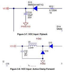
Secondary side MOSFETs and gate drive circuit, and an output inductor: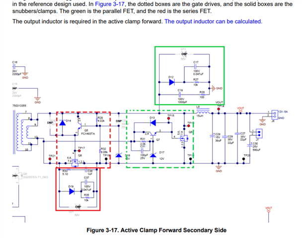
2. PMP21318: 12V/ 6A reference design
PMP21103: 12 V/ 2.5A reference design
3. Debugging guide: PoE Powered Devices Debug Guidelines
Let me know if I can provide any further help.
Best,
Sarah
Hi Sara,
Is the debiug guide "PoE Powered Devices Debug Guidelines" also for ACF? or just for flyback?
BRs
Peter Hsiao
0938286682
Hi Peter,
I will close this thread for now. Please reply or open a new thread if you have further questions.
Best regards,
Diang