This thread has been locked.

If you have a related question, please click the "Ask a related question" button in the top right corner. The newly created question will be automatically linked to this question.

TPS2597: Inrush current has high peak

Part Number: TPS2597
Other Parts Discussed in Thread: TPS63811

We are using the TPS25974L in the circuit shown below:

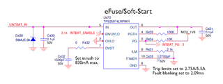
The output of the eFuse is connected to circuitry that includes 380uF of capacitance. 

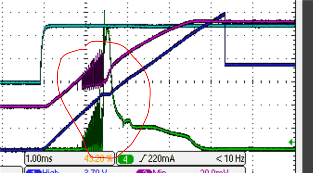
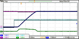
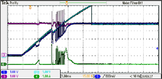
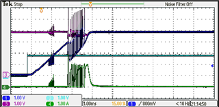
When the eFuse is enabled we see a current spike that looks excessive:

Dark blue = ITIMER pin 10, light blue = dv/dt pin 7, purple = output voltage pin 6, green = input current

The current spikes to approx 3A for a short time. My understanding is the eFuse should hold the current to under 830mA with these component values. 

Is this correct operation?

  • Today is a holiday for TI India due to the Independence Day of India. We will get back to you on Wednesday.

  • Hi Rob,

    Where are you measuring current?

    Regards

    Kunal Goel

  • Hi Kunal,

    I am measuring the current into the eFuse.

    This is part of a battery powered system and the inrush current control (dv/dt - pin7) of the eFuse is being used to control a turn on current surge from the battery. 

  • Hi Rob,

    eFuse is controlling VOUT slew rate. So current through eFuse is cap charging current +LOAD current. Cap charging current is COUT*dv/dt= 830mA. eFuse will allow current upto ILIM. 

    Regards

    Kunal Goel

  • Hi Kunal,

    The load is 380uF cap and input to a TPS63811 boost converter. At time of eFuse turn on the TPS63811 is not configured or enabled so its loading should be minimal. As I read the datasheet, the eFuse should simply be controlling the charging of the cap and holding the charging current to 830mA in this circuit. Why is the eFuse allowing this current spike when enabled?

  • Hi Rob,

    Please capture VIN also. Since current is at input side it will also show input cap charge current. Due to VIN fluctuations input cap will charge/discharge. So it could be the current peak is due to input cap.

    Regards

    Kunal Goel

  • Hi Kunal,

    There is only a .1uF cap at the input. Could that actually be causing this issue? 

    I have a 4 channel scope. What exactly signals would you like to see so that you may explain this operation.

  • Hi Rob,

    Input cap will draw current that depends on VIN slew rate. 

    I will recommend test by completely isolating eFuse VOUT from boost converter(any other downstream load) and remove input cap.

    Please monitor (VIN,VOUT, input current, dvdt) ,  (VIN,VOUT, input current, EN)

    Also something weird is happening here: Please make sure that probe is fine and connections are fine. 

    Regards

    Kunal Goel

  • Hi Kunal,

    I agree, something weird is happening in the plot I sent. I checked my probes and connections and they are all good.

    Here are additional scope captures that you requested. In the following scope captures the dark blue = VOUT, purple = VIN, light blue = dvdt, green = input current. In the second capture the light blue = EN


    This is with no input cap and the output isolated from all other devices. There is only a .1uF on the output.


    This is with adding 330uF cap to output.


    This is connected to the TPS63811 buck-boost converter. I verified that the TPS63811 is disabled at the time that the eFuse is enabled. 

    While it is obvious that the addition of the TPS63811 is causing the issue, it is not obvious why the eFuse is not doing a better job of limiting the inrush current. As we have the circuit setup per datasheet formulas, I am thinking the eFuse should hold the current spikes to under 1A.

    Is the eFuse operating correctly?

    Should dvdt rise to nearly 6V?

    Do we have the circuit configured correctly?

    Any suggestions on how to reduce the inrush current spikes?

  • Hi Rob,

    Dvdt behavior is fine. It will go above VIN level. Your current limit is 2.75A so eFuse will limit below it . 

    Limiting to 830mA is valid when load is capactive in that case current through eFuse will go though cap only.

    IeFuse= C*DV/DT= Constant at 830mA

    But in your case dc-dc is also drawing current so eFuse has to support both cap and dc-dc.

    IeFuse= C*DV/DT+ ILOADDC_DC <=ILIM

    What is the exact concern with current spikes?

    Regards

    Kunal Goel

  • Hi Kunal,

    Just to make sure I understand this correctly. The dvdt  input is really just controlling the gate on the power MOSFET in the eFuse. The eFuse is not doing any active current limiting during turn on. Controlling the gate would be similar to replacing the power MOSFET with a variable resistor. In that case, the turn on process is where resistance is decreased from extremely high to almost zero over a couple of milliseconds.

    For constant capacitive load we will see a limited rise time which limits the charging of the cap. As the cap charges the current demand decreases as simultaneously the power MOSFET on resistance decreases.  For the switching load, as the power MOSFET series resistance decreases more current is available to the switching load to allow it to start up. 

    Do I have this right?

    The concern with the current spikes was mainly to limit high current events that the battery in our system will see. Additionally, we want to make sure we understand the actual circuit operation as opposed to what we think the datasheet is describing as correct operation.

  • Hi Rob,

    You are correct on understanding. But we have both inrush current control and current limit during startup also. Inrush current control is ramping up FET gate with a controlled slew rate. It is a source follower. VOUT will follow gate slew rate. Now current through eFuse is (VOUT/RLOAD + COUT*dv/dt). If load current crosses current limit eFuse will limit it. Current limit has a response time of 465us. So if current peak is less than 465us then device might not limit it. 

    I think since current peaks in your case are less than 100us so eFuse might not be limiting them.

    I think some path in buck-boost is getting enabled. We also need to see if we can disable that path while eFuse is starting up.

    Regards

    Kunal Goel

  • Hi Kunal,

    We are using the eFuse to control turn on currents in the rest of the circuit and minimize the current spikes seen by the battery. This is not a good as we had expected but good enough to satisfy the requirements.