This thread has been locked.

If you have a related question, please click the "Ask a related question" button in the top right corner. The newly created question will be automatically linked to this question.

TPS62933: TPS62933 overfrequency in Power Designer

Part Number: TPS62933

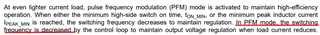
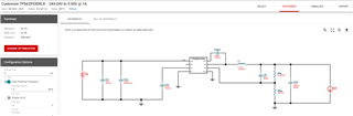
I'm modelling a buck converter based on TPS62933 chip in Webench Power Designer.

The input data is as follows: 24V in, 5V out, 0-1A output current, 1.2MHz output frequency. Everything else is in default state.

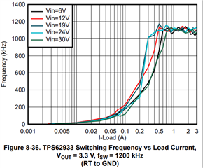
When then entering in "operation values" tab Vin = 24V and Iout from 0.23 to 0.375A, Power Designer outputs the resulting switching frequencies over 1.2MHz (up to 1.96MHz). When current goes from 0.375 to 0.376A, the frequency drops from 1.96 to 1.2 MHz in one step (I guess, it has something to do with min IL peak-to-peak value = 0.75A, like 0.375A is a half of it).

Nowhere in the datasheet I found mentions about conditions where switching frequency can go over the desired value, especially that much over (it can only be decreased by chip logic in PFM-mode due to frequency foldback).

If I choose 2 MHz as a desired switching frequency, the actual frequency shown goes over 2.4 MHz which is way bigger than absolute maximum 2.2 MHz frequency.

So is there a Power Designer model problem, or I'm missing something?

Thanks.

P.S. I can go for "simulation" mode, that often shows more expected results, than "customize" mode, however, this mode simulates only a few basic parameters, and completely misses some, like efficiency, power dissipation, junction temperature etc (which are present only in "customize" mode and are calculated based on the mentioned above values, so they are probably erroneous too).


  • Hi Aleksei,

    It's always to hard to accurately calculate decreased fsw during PFM operation. You may use webench simulation results as a reference, but hard to get an accurate value of decreased fsw.


    If you want fixed fsw among full loading range. Please choose the FCCM part -- TPS62933F, which sacrificed light-load efficiency (higher fsw, larger switching loss than PFM part), but fsw keeps fixed.

  • I think this is not a matter of calculation accuracy, Power Designer is missing something more important.

    For example, with 15uH inductor and 24Vin and 5Vout it is physically impossible to reach switching frequencies of 1.2MHz or 500kHz with ANY desired output current and any conducting mode (CCM, DCM, PFM, doesn't matter) just due to the inductance value and claimed min. required inductor ripple current of 0.75A (with given driving voltages, to go up +0.75A across the given inductance and back again takes more time than a 500kHz switching period, so Fsw would always be less than that).

    Min. rise time would be 15uH*0,75A/(24V - 5V) = 592ns

    Min fall time would be 15uH*0.75A/5V = 2250ns

    So maximum switching frequency would be 1/(592ns + 2250ns) = 352kHz and can never hit neither 1.2MHz nor 500kHz. So Power Designer output is nonsensical. OR the IC somehow can operate with peak-to-peak inductor current less than 750mA. Correct me if I'm wrong.

  • Hi Aleksei,

    My colleague will give you reply soon!

    BRs

    Zixu

  • Hi Aleksei,

    If using 24Vin, 5Vout, 1A, 1.2MHz to generate webench design, I got 2.7uH recommended inductance, not 15uH.

    Then the calculation will be:

    Min. rise time would be 2.7uH*0.75A/(24V - 5V) = 107ns

    Min fall time would be 2.7uH*0.75A/5V = 405ns

    f=1/(107ns + 405ns) = 1.95MHz, which match webench results that you mentioned.

  • Besides, the simulated frequency jump won't happen on actual device behavior. Datasheet gives fsw vs Iout curve, which you may refer to.

  • In PD I can redefine the inductor value, so I did it for the value we have in stock (15uH), which better satisfies our needs for very light load operation mode and no fast transients. But it didn't affect the resulting frequency at all.

  • Yeah, I've seen that. It has a few problems:

    1. It doesn't take the inductance value chosen into account.

    2. It doesn't match the simulation results (presumably due to p.1).

    3. It never oscillates on the desired 1.2MHz frequency, being at least 100kHz lower all the time.

    4. I can't understand why for some current values a 24V plot is 1.5x times higher than a 12V one, and for slightly lower currents it is now 1.5x times lower. It doesn't make sense, like it is not the mathematical approximation of the IC, but some random one-time measurements.

  • Hi Aleksei

    My colleague will give your feedback today later, thanks!

  • Hi Aleksei,

    Thanks for helping us find the simulation error. I will feedback this to webench team. 

  • Hi Aleksei,

    I found you rejected my answer, may I know your further support need?

    I'm afraid the webench simulation error cannot be fixed in short time. Webench uses a simple model, not Candence model that our IC designers used, the simple model cannot perfectly model all device behaviors. As I said previously, datasheet already gives fsw vs Iout curve, which shows NO fsw jump actually. I think what you really care is device actual performance, and datasheet shows there won't have the fsw jump that you worried about. What's your further questions?

    Feel free to let me know. Otherwise I will close this thread.