This thread has been locked.

If you have a related question, please click the "Ask a related question" button in the top right corner. The newly created question will be automatically linked to this question.

LM5030: LM5030

Part Number: LM5030

Dear  Mr.

Design is Vin=17-28V, Vout=250V, Iout=1A, Fsw=250kHz, LM5030

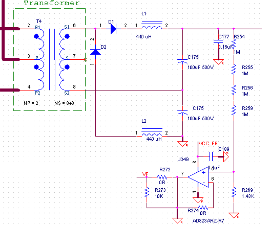
My push-pull transformer haven't enough output voltage and I going to use voltage doubling rectifier 

It is working excellent with sinusoidal signal, but here square wave signal and I have to add L1&L2 I think.

Is schematic right ?. If yes...What is the criterion for choosing an inductance? (With 440uH I'm not happy)

Regards

Mikhail

  • Hi,

    The doubler circuit looks ok to me. I think the inductance value should be determined by the amount of energy to be transferred to load. Is your circuit in DCM or CCM. If in CCM, then the energy to be transferred would be the energy at peak current minus energy at end of the cycle. That energy has to be sufficient to balance the load energy requirement. Since each inductor only deliver energy in half time, but you would need the voltage doubled, then each inductor would need to have 2x load energy.

    The square waveform through LC would become not square so you won't get doubler with flat voltage at C175 - this is not like sine waveform. The transformer output square would make C175 more like sine waveform with peak at much higher. So your circuit won't make a flat doubler - it looks like your would need some additional circuitry to help.

    A possible way is to make the inductor value small, then you can get flat voltage at C175, then C175 value has to be large.

    Or you do not use voltage doubler, but use a boost converter at the secondary side to boost the transformer DC to what you need.