This thread has been locked.

If you have a related question, please click the "Ask a related question" button in the top right corner. The newly created question will be automatically linked to this question.

BQSTUDIO: BQ34Z100-G1

Part Number: BQSTUDIO
Other Parts Discussed in Thread: EV2400, BQ34Z100EVM, BQ34Z100-G1

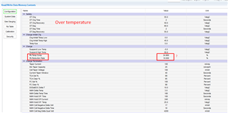
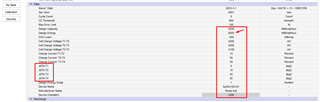
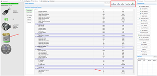
I am getting this error when i select desire chip in bqstudio. What i should do for it?

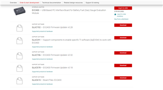
Also, i have EV2400 with firmware version 0.18. What version should i install it from website because there are 3 versions available? what's the difference?

Last, i checked some videos about golden image programming of BQZ. Is there any document that i can follow to setup for the battery?
The three video's available for it but they do voltage/current calibration. I just want to evaluate simple mode but not advance for the sake of learning and testing.

  • Hi Ali,

    When selecting a gauge, that issue will occur if the gauge is not connected to the EV2400 or is not communicating to it. If the gauge is communicating correctly with EV2400, BqStudio should immediately open without prompting you to choose a gauge. 

    The downloadable firmware updater versions for the EV2400 are based on improvements and bug fixes that have been added over time, with v0.32 being the most recent and v0.18 being the least recent.

    Regarding documentation to set up the battery, the link below is the User's Guide for the bq34z100EVM which could provide assistance.

    https://www.ti.com/lit/pdf/sluu904 

    Regards,

    Anthony

  • Thanks
    Yes, gauge wasn't connected with the EV2400.
    Thanks for your help.
    I will look into the guide and if i need any assistance, will get back to you. In the meantime, it would be great if we keep open this channel.
    Thanks

  • Hi

    I was able to communicate guage with EV2400.
    Now i am facing some issues if someone can answer. I followed current and voltage calibration videos of TI

    1.  If current 1A is consuming by load then i should enter -1000 value or 1000mA. In the video, they put - value. Why?
    2. I tried to voltage calibration but unfortunately, the default voltage are far lower than input voltages. If i apply 10V then i see in the BQstudio 250mV or something like that. If i try to calibrate it then it won't let me enter value more than 1V and give error that is beyond limit
    3. Is it something to do with other settings? Current calibration was successful but i entered - value to calibrate. Not sure if it is the right way or not.
    4. After all these calibrations, how i can save this file in my computer so next time, i open it all settings are there? Also how i can reset settings to default?

    Thanks

  • Hi

    Is there any update plz?

    Thanks

  • Hi Ali,

    1. Since the system is consuming current, the value will be negative. If the system were to supply current, this value would be positive.

    2. These steps can be taken to complete voltage calibration:

    • First, orient the jumpers on the EVM for a voltage input below 5V. This can be done by moving the two jumpers on J5 to the =<5 pins.
    • Next, supply the EVM with an input voltage below 5V and open bqStudio.
    • Once bqStudio is opened, make sure that the correct input voltage is being displayed on the dashboard.
    • Go to Data Memory -> Configuration -> Power and change the Flash Update OK Cell Volt value from 2800 mV to 0 mV. Press Write_All in the top right corner.
    • Next, reorient the jumpers on the EVM for an input voltage greater than 5V, and supply the EVM with the desired voltage. Reopen bqStudio.
    • The next step it to change the VOLSEL bit from low to high. Go to Data Memory -> Configuration -> Registers -> Pack Configuration and select the value box.
    • This should open a window with the individual bit values. Select the VOLSEL bit and select write to register.
    • Select RESET in the command window and confirm that the bit has changed in the register window. VOLSEL should be red now.
    • Calibrate the voltage as seen in the video.

    When deploying this device, make sure that the Flash Update OK Cell Volt is changed back to 2800 mV.

    3. Since these values are written to the registers, it will not change and will show the correct value anytime bqStudio is opened. To reset to the default, the easiest way is to upload the original firmware to the device.

    Regards,

    Anthony

  • Hi
    Where i can get each register setting detail information to better understand the function of everything?
    Also, i made a custom board and it is expecting voltage more than 5V. So i don't have 5V feature for it. Can i still apply the 5V?
    I followed the datasheet reference design for multicell.
    Thanks

  • Hi Ali,

    The details for each register setting can be found in the bq34z100-G1 Technical Reference Manual below:

    https://www.ti.com/lit/pdf/sluubw5 

    On your custom board, is there a way you can supply between 2800mV and 5000mV directly to the BAT+ and BAT- pins of the bq34z100-G1 device? If this is possible, you will be able to toggle the VOLSEL bit and complete the voltage calibration.

    Regards,

    Anthony

  • Hi

    Is it necessary to appl y voltage less than 5V at BAT pin of IC?
    This is the circuit that i am using.

    What if i apply voltage 6V at BAT+ connector pin and then check voltage at BAT pin of IC. If it is 5V then can it work?
    Or the voltage must be lower than 5V?

    Thanks

  • Hi Ali,

    After looking through your circuit, we have realized that the gauge will not function with a voltage lower than 5V coming from where you have the battery. However, to get the VOLSEL bit changed and complete the voltage calibration, we still need a voltage between 2.8V and 5V entering the BAT pin.

    I believe the best course of action is to input a voltage between 2.8V and 5V on the node between R15, R18, C12, and the BAT pin, while also still powering the circuit from the designated BAT+/BAT- section of the circuit.

    Regards,

    Anthony Baldino

  • Ok, I can do this manually.
    i will follow all these steps now.

    • First, orient the jumpers on the EVM for a voltage input below 5V. This can be done by moving the two jumpers on J5 to the =<5 pins.
    • Next, supply the EVM with an input voltage below 5V and open bqStudio.
    • Once bqStudio is opened, make sure that the correct input voltage is being displayed on the dashboard.
    • Go to Data Memory -> Configuration -> Power and change the Flash Update OK Cell Volt value from 2800 mV to 0 mV. Press Write_All in the top right corner.
    • Next, reorient the jumpers on the EVM for an input voltage greater than 5V, and supply the EVM with the desired voltage. Reopen bqStudio.
    • The next step it to change the VOLSEL bit from low to high. Go to Data Memory -> Configuration -> Registers -> Pack Configuration and select the value box.
    • This should open a window with the individual bit values. Select the VOLSEL bit and select write to register.
    • Select RESET in the command window and confirm that the bit has changed in the register window. VOLSEL should be red now.
    • Calibrate the voltage as seen in the video.

    When deploying this device, make sure that the Flash Update OK Cell Volt is changed back to 2800 mV.

    Can you explain a bit more about point 3? If correct input voltage not displayed on the BQstudio then what? I am sure, it will not because when i applied voltage more than 5V. it was showing in mV.
    Will it show the correct voltages when i will directly apply the 5V at BAT pin?
    Thanks again for your valuable information.

  • Hi Ali,

    Regarding point 3, bqStudio should show the correct voltage when you input directly into the BAT pin with less than 5V, also any voltage that is shown in bqStudio is always shown in mV. The issue that you are having with the incorrect reading in the mV once you input more than 5V is what we believe to be a saturation issue, however reading values below 5V should not be an issue. 

    However, I would not directly put 5V into the BAT pin since it is on that threshold of the error. I would input somewhere around 4V since the aim is to be between 2.8V and 5V.

    Regards,

    Anthony Baldino

  • Hi
    I followed all your steps except when i opened the BQstudio(point3) it wasn't showing me applied voltage that i applied at BAT pin directly i.e2.5V
    What i did, calibrate the voltages to 2500mV according to the video and it start showing the applied voltage.
    Next i followed all your steps and it started working to show me voltages as i increased on supply voltages i.e. 10V
    Now, I need to understand what it means?
    Also,

    When deploying this device, make sure that the Flash Update OK Cell Volt is changed back to 2800 mV.

    I attached the datasheet of battery.
    What other steps i should consider while calibrating it?
    How i can upload the permanent image into the IC so i don't have to do all this calibration again and again corresponding to that battery.
    Thanks
    4113.Battery datasheet.pdf

  • Hi Ali,

    If the dashboard on bqStudio is showing the correct value after the calibration steps have been taken with your battery pack attached, then it was successful. To avoid doing the calibration steps again, the .SREC files can be downloaded from the Golden Image tab of bqStudio to get a copy of the image, and can be reloaded using the Programming tab of bqStudio.

    Since the settings have been written onto this device, the settings will remain even if it is depowered.

    Regards,

    Anthony Baldino

  • There are many parameters that i wasn't able to setup yet.
    Like capacity of battery, max and min range.
    series cell configuration and so many things.
    Now the final question is after this calibration whatever battery pack, i will connect. It will recognize it's voltages but i belive, it will not spit out correct information of the pack unless i setup each register.
    I study about it in datasheet.
    Let's say i setup every register. Now what should be the final step to save settings in the IC.
    Write all, or programming or what?
    Thanks

  • Hi Ali,

    In bqStudio, when values are inputted they are automatically written to the device. If you are looking to save the image of the settings to use on a different IC that has not been calibrated, you can save the image as an .SREC file from the already calibrated IC in Golden Image, and program it to the new IC in the Programming tab.

    Once this is all completed, the next steps you will want to take are determining a ChemID for the chosen battery, and preforming a learning cycle for the battery found in sections 11.1 through 11.3 of the bq34z100-G1 Technical Reference Manual attached below.

    https://www.ti.com/lit/pdf/sluubw5

    Regards,

    Anthony Baldino

  • Hi

    I am studying all the documents and i am getting a lot of information. I have some questions if you don't mind to answer plz.

    1. The 1st four classes are almost setup at by default values and i believe they are good as general. Correct?

      Only two parameters aren't at their default values. Should i change them to default? What are the major impact of these parameters other than safety?
    2. I couldn't find LIION battery in the chemistry list. I even updated list from 665 to 1045. I also attached the datasheet of my battery.

      By default, it says LIION but i want to know how i can select it in the list if any case i lost it in settings.
    3. The battery that i am using has 2.5Ah cell in 7S1P configuration. The total energy is 63Wh but i couldn't add it's value in the desire box
    4. I also noticed that now with some settings, the gauge now showing 7% of battery power even if i am applying 25V through power supply. The nominal voltages of the battery are 25.2V

      Last, what is the purpose of Write_ALL and READ_All button?

    KAMADA 24v2.5ah 7S1P specs 中英文规格书.pdf

  • Hi Ali,

    1. For the Pb Temp Comp and Pb Reduction Rate values, there seems to be an issue with the values we have in the Technical Reference Manual. We believe the values you have there should be fine. 

    2. The link below should assist you in finding the correct chemistry for the battery you are interested in using:

    https://e2e.ti.com/support/power-management-group/power-management---internal/f/power-management---internal-forum/1262123/bq40z80-learning-cycle-difficulties

    3. We believe that this design energy value should not be changed unless you are planning to constant power load and change the load mode to 1.

    4. Since a learning cycle has not been preformed for this battery yet, this is fine. Once all the processes have been completed for this battery, bqStudio will show the correct value.

    5. The purpose of Write_ALL and Read_ALL are to configure settings to the gauge if you are importing a .GG file containing an image of other settings.

  • Hi
    Sorry to interrupt you again. I didn't expect that much of complexities from a simple gauge but the good thing is learned a lot.
    I don't think so i am able to define Chemistry ID part. Is it true that by default it setup LIION ID. If that it is then i am also using the same battery.
    The next thing is learning cycle. I believe these are the steps that i must do for it.
    1: Discharging until cutoff voltage
    2: wait
    3: Charging until taper current
    4: wait

    Now how many times, i have to do it for the fuel gauge to understand it? Is there some kind of other settings that i must take care while this learning cycle.
    Thanks

  • Hi Ali,

    Those are the correct steps that need to be done for the learning cycle. The learning cycle only needs to be done once.

    The Technical Reference Manual below has instructions to achieve this, along with solutions to common issues that can occur in sections 11.3 - 11.5:

    https://www.ti.com/lit/pdf/sluubw5 

    Regards,

    Anthony Baldino