This thread has been locked.

If you have a related question, please click the "Ask a related question" button in the top right corner. The newly created question will be automatically linked to this question.

TPS3840-Q1: question about TPS3840-Q1 tSTRT + tD time

Part Number: TPS3840-Q1

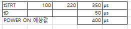
TPS3840-Q1 tSTRT + tD time is measured differently from the datasheet value.

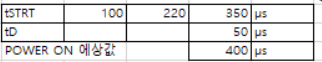
The datasheet shows 400us as the maximum value.

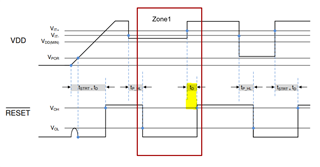
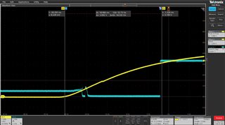
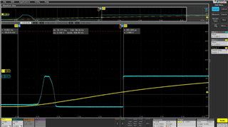
When I actually measured it, it came out about 10 ms as shown below.

Please find the cause why.

  • Hi Hansook,

    I want to let you know that I'll reach back to you by the end of the week.

    Best Regards,

    Sila Atalar

  • Hi Hansook, 

    Can you please provide what threshold voltage value you are using and what are you measuring on channel 1? 

    Best Regards,

    Sila Atalar 

  • The yellow figure is the vdd voltage, and the sky blue figure is the reset waveform. It is designed to detect vdd voltage at 3.0 voltage.

  • Hi Hansook, 

    I would  recommend you to change your voltage divider resistor values. Since it is not set to 3V right now. 


    As long as VDD below the threshold voltage the device keep asserting (low). In this case VDD is below threshold for 10 ms, that is why you are measuring your tstrt+td longer. 

    Best Regards,

    Sila Atalar

  • This waveform is the measured waveform when VDD is from OFF to ON.

    This also differs from the values shown in the datasheet.

    The datasheet specifies a time up to 400us from the VDD ON point as above.


    ...

    But on the waveform I measured, it takes about 10 ms.

    Please reply about what causes the difference
  • Hi Hansook,

    Thanks for pointing out this problem on the datasheet. We will change the timing diagram in our next revision since beginning part causing misunderstanding.

    Please look at the zone1 to understand correct td time delay behavior. As long as Vdd is under threshold voltage TPS3840-Q1 reset output should be asserted. After it passes positive threshold voltage (Vit+) td time later reset output can be un-asserted.

    Correct time equation for the start condition should be tstrt + td + trise. ( trise =  the time Vdd reaches Vith+ )

    Regards,

    Sila Atalar

  • Is Vith+ of trise time 3.1V right? In that case, it is difficult to measure the time as the following waveform appears.

  • Hi Hansook,

    If you look at the functional block diagram, this device has already fixed threshold (internal voltage divider). Putting high impedance on the may cause the issue you are experiencing. 

    I would recommend using smaller impedance for voltage divider on the Vdd pin.

    Please let me know if you have the same problem  with  different less impedance on the VDD pin. 

    Regards,

    Sila Atalar