A related question is a question created from another question. When the related question is created, it will be automatically linked to the original question.
If you have a related question, please click the "Ask a related question" button in the top right corner. The newly created question will be automatically linked to this question.
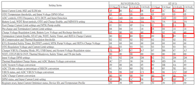
During the ESD test, I found that the LED was flickering. After reading the register, I found that there was an abnormality in the Flag test. From which Flag can I find the problem? Thank you.
In addition, the customer found the adapter AC ON/OFF test with QUAIL V2(NUVOTON MCU) and battery. Turn on→Turn off(about 700mS to 800mS)→ Turn on again Such a test will also find the same situation as the surge test.
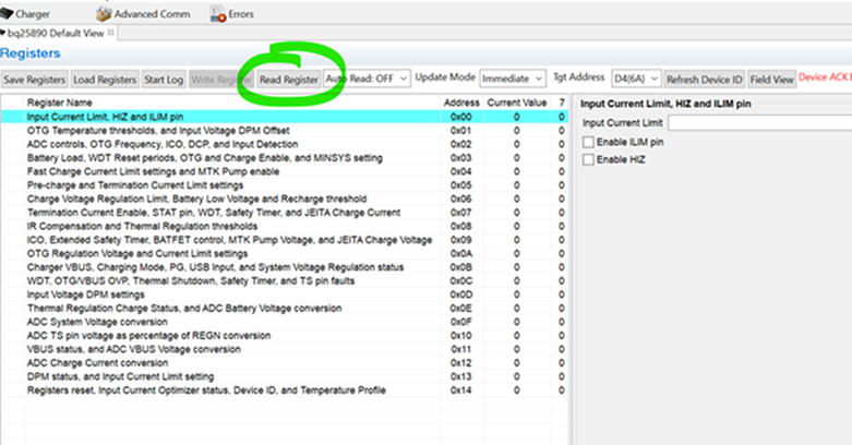
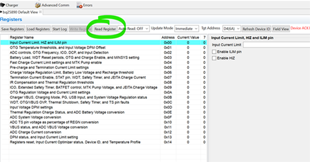
Please help to check the register, if there has any fag can find the problem? Thank you.
I have reviewed the registers attached and they do not show any fault conditions on the charger. Please help to answer my questions from my previous response as well as explain the problem the customer is seeing in more detail. Based on your current description I cannot tell what issue the customer is facing.
Excuse me, I reorganize the current situation as the following.
By the test. ST and NUVOTON MCU is still alive and the two I2C bus worked well when the ESD discharging issue appeared. Please check whether the BQ25895RTWR register recovers to the default value when 12V deep drops. And please advise what situation that second LED will light up by FW. Thanks.
-When you say the LED was flickering are you referring to the LED connected to the STAT pin?
Ans: The STAT pin is floating. and the LED connected to MCU
-Can you please help to share all operating conditions during this test such as VBUS, VBAT, VSYS, etc.?
You mention the LED is connected to the MCU. Since it is not an LED connected to a BQ25895 pin I am not able to comment on this LEDs expected behavior.
When 12V supply at VBUS is removed if a valid battery remains connected to BAT pin registers should not reset to default. Registers are expected to reset to default when there power lost at both VBUS and BAT pins.
In the provided waveform capture what is the blue signal measuring? I do not know what TP8 / TP14 is referring to.


 '
'