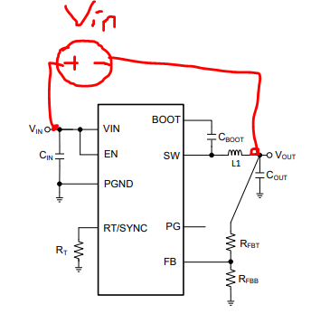
Hi, can you please suggest the IC for generating clean +15V/5W and -15V/5W power supply from 24V input to be used for current sensor power supply.
Regards,
Jitendra
This thread has been locked.
If you have a related question, please click the "Ask a related question" button in the top right corner. The newly created question will be automatically linked to this question.
Hi Jitendra,
What is the max VIN including transients?
Thanks!
-Tahar
Hi Tahar,
24 V is regulated supply. Max VIN is 28V. Also the power mentioned, 5W, is peak power. Average combined power is 2 W.
Regards,
Jitendra
Hello Jitendra,
I found couple devices from WVIN team, I assigned you post to them to comment more.
https://www.ti.com/product/LMQ66410
Thanks
Tahar
Hi Jitendra,
We have other parts but you can use the LMQ6410 for the +15V. However, for the -15V which requires an inverting buck-boost topology, which can be done with a buck device--See the following article by our colleague https://www.ti.com/lit/an/snva856b/snva856b.pdf. However it will require an IC with a Vin rating greater than >43V (assuming your max vin is 28V). I would suggest LMR36510 in the inverting buck-boost configuration to produce -15V.
Yes you can also use it to produce +15V if you want to select the same parts.
Best Regards,
Youhao
Hi Youhao,
Thanks for suggesting LMR36510. Yes, I need to have same part.
400 kHz switching frequency is comparable to the current frequency that we want to measure. Can you suggest part with higher switching frequency.
Regards,
Jitendra
Hi Youhao, ok.
LMR38020 datasheet is not available. It is showing Error 404. Can you share it here?
Regards,
Jitendra
Hi Youhao,
Thanks.
How can we do transient simulation of LMR38020 inverting buck boost.
Regards,
Jitendra
Hi Jitendra,
Use the transient model, and reconfigure the external circuit as an inverting buck boost. You should also pay attention to the ground references. I think 0V gnd of the model maybe a global 0V net, therefore, you may need to consider a level shift in setting up your Pspice model. By doing the following:
1. Set IC GND pin to 0V, or connected to the Pspice GND symbol.
2. Set your actual system GND to be Vout, not connecting GND symbol.
3. Connect VIN source from VIN pin to Vout node which you assigned in above step.

The Vout from the simulation would be a positive voltage. The GND symbol is your actually negative output port if the Vout node is shifted down to 0V.
Hope this clarifies,
Thanks,
Youhao
Dear Youhao,
Thanks. We are looking at it.
I need one more suggestion for the design. We expect 500mV/500 kHZ noise at the input of the regulator. What additional can I do to reject it nicely.
Regards,
Jitendra
Dear Youhao,
Thanks.
Webench suggested inductor value of 8.2uH for buck configuration. With 8.2uH, calculated current ripple is very small at 2MHz. Also section 9.2.2.4 in the datasheet says "Note that when selecting the ripple current for applications with much smaller maximum load than the maximum available from the device, use the maximum device current." Datasheet based calculation suggests to use much smaller value of inductor.
For simulation with 8.2uH, it seems device is not working in normal mode. Device behaved normally with 2.2uH in simulation.
Can you please suggest the good current ripple level for this device to choose proper inductor value?
Regards,
Jitendra
Hello Jitendra,
Monday is a US holiday.
Please expect some additional comments tomorrow.
Regards,
Denislav
Dear Youhao,
How are you doing?
Do you have any suggestions for the inductor value and current rating. We want to finalize the inductor specs.
Regards,
Jitendra
Hi Jitendra,
Sorry for the delay. The ic is 2~3A pk current capable, and your max load current is just 0.33A, about 10% of the capability, and it can be considered as "much smaller" or you can think it is still in normal range. In my understanding, 8.2uH should work, but 2.2uH may perform better according to the referred datasheet recommendations. Also, 2.2uH may be cheaper.
The Webench is based on EVM, a proven circuit design, and it may be limited to optimize the design. However, it should work, at least getting you to a good start point. We always recommend the customers to adjust the circuit by experiment to get better performance.
Wish you good luck in your project.
Best Regard,
Youhao