


Hi
Previously, the load control system was developed using 76940. The system had a signal line KEY and a total positive B+output from the battery, as well as a total negative P - output from the battery. Among them, B+refers to the total positive voltage of the battery that cannot be directly discharged from the board, P - refers to the negative voltage controlled by the board, and KEY line is the signal that activates the system.
When the customer uses it, connect KEY to B+, and the system activates and starts working.
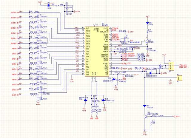
Now it is necessary to change the system to the control system of 76952, but the logic of using the KEY line remains the same.
In a negative control system, the output positive pole is not controlled and is a constantly charged excitation source, which can be used to excite the KEY circuit.
However, in the control system, it is always controlled and cannot provide an excitation signal when the discharge MOS is turned off.
To make a signal wire connected to P+ that can activate the system. But this contradicts the LD wake-up logic of 76952.
Connect P+ from DET2 and pull low the TS2
Please give some suggestions.
Thanks
Star
