This thread has been locked.

If you have a related question, please click the "Ask a related question" button in the top right corner. The newly created question will be automatically linked to this question.

LM5160A: Operation on PSpice

Part Number: LM5160A
Other Parts Discussed in Thread: LM5160,

Dear TI team


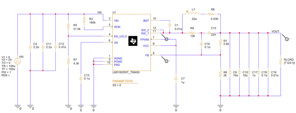
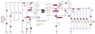
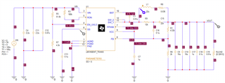
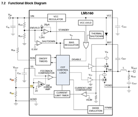
I'm running a simulation of the LM5160 on PSpice.

I was able to confirm that it basically works as intended.

However, there is one thing that bothers me, and I am contacting you.


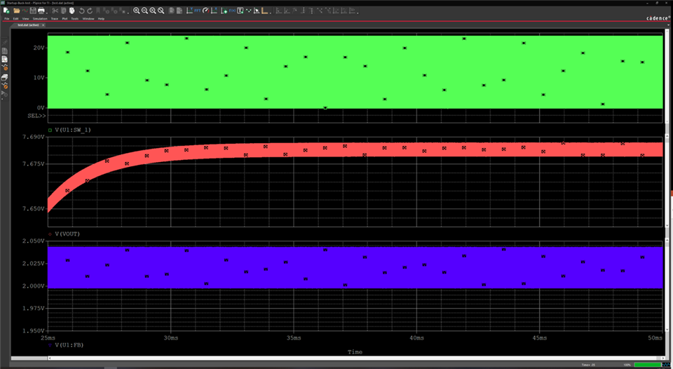
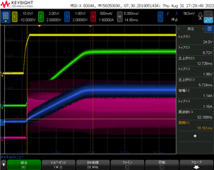
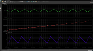
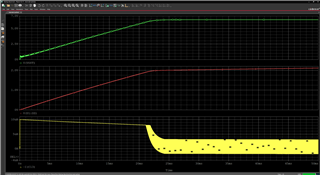
The bottom voltage of VFB stabilizes at 2.0V after the soft-start time has elapsed after power-on.

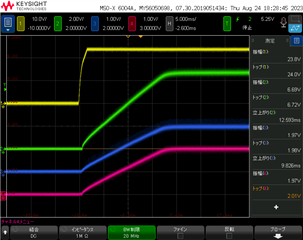
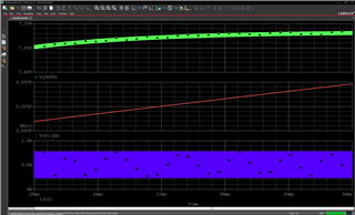
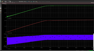
Therefore, I think that VOUT stabilizes at least at 25msec in the waveform below.

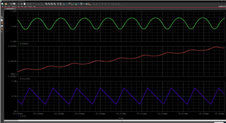
However, in the simulation results, the voltage seems to rise up to about 33msec.


Please let me know if you have any ideas as to why this is the case.

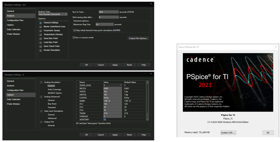
We will also send you the simulation settings and tool version just in case.


Best Regards,

Taroimo

  • Hi Taroimo,

    Thank you for posting. What you see is an closed loop operation behavior, and when SS completes, the feedback ref voltage establishes but the circuit still takes time to catch up to get the output regulation.  The delay is normal in the feedback controlled circuit. 

    Hope this clarifies.

    Best Regards,

    Youhao

  • Hi Youhao,

    Thank you for information,

    I measured the startup with the same circuit diagram as the PSpice model.

    (Vout is slightly different, but all other circuits including Css are the same.)

    The actual rising waveform did not generate any delay other than Css: 0.1μF = 20ms.

    Would you let me know about the conditions that cause a delay and the cases where a delay of 8ms actually occurs?

    Or could it be something that only happens in PSpice simulations?

    ※ch1: Vin, ch2: Vout, ch3: Vss, ch4: Vfb

     Iout condition is 1A, and the waveforms at 0A and 500mA were almost similar.

    Best regards,

    Satoshi

  • Hi Satoshi-san,

    There is no fixed 8ms delay inside the model. Before SS voltage reaches to 2V, the SS voltage is the feedback reference voltage.  After SS reaches 2V, the internal 2V reference takes over as the feedback reference voltage. Depending on the loading conditions, you may or may not see some output voltage delays.  Also note that the current limit can also plays a role in affecting the Vout rise time. In the model the current limit is modeled at its typical value, but the IC that you use may have a higher current limit than the model has. 

    To further investigate this, could you monitor the inductor current, and SS voltage during startup in your simulation?

    Thanks,

    Youhao

  • Hi Youhao san

    Thank you for reply,

    Once the simulation data is complete, we will send it to you, so please take a moment to send it to us.

    For your reference, the actual measured waveforms are attached.

    Current limit is not reached and tss is about 20ms, as calculated.

    ※ch1: Vin, ch2: Vout, ch3: Vss, ch4: IL, Iout:1A

    Best regards,

    Satoshi

  • Hello Satoshi, 

    Sept 4 is a US holiday. Please expect some additional comments tomorrow.

    Regards, 
    Denislav

  • Hi Youhao,


    We will send you simulation waveforms that monitor the inductor current and SS voltage during startup.

    (This circuit is the same as the previous simulation.)

    Even after SS reaches 2V, the output voltage continues to rise slowly.

    Should I assume that it takes time for the feedback reference voltage to switch to the internal 2V reference?


    Best Regards,

    Taroimo

  • Hi Taroimo-san,

    After SS reaches 2V, SS will hand over the control of the FB ref voltage to the internal 2V reference voltage, that means the SS is no long in control. There should be no transition time for the handover.  However, the reference voltage handover does not mean Vout also reached the setting point.  

    I am looking forward to see the inductor current sim waveform in order to tell if the current limit delays the Vout rise.

    Thanks,

    Youhao

  • Hi Youhao,


    We will send you a simulation waveform with an expanded time range so that you can see the inductor current waveform.

    The first image shows the area from 25.00msec to 25.02msec, and the second image shows the area from 30.00msec to 30.02msec.

    Also shown in the bottom plot is the inductor current trace.


    Best Regards,

    Taroimo

  • Hi Taroimo-san,

    Thank you but in these time intervals the Vout is already in regulation:  7.6V, also see you average inductor current already reached 0.5A.   Can you show the sim results similar to the experimental results as shown below?  Namely having the similar signal and similar scales in vertical and horizontal for each signal, so we can have a comparison?

    Thanks,

    Youhao

  • Hi Youhao,


    We will send a simulation waveform in the 0~50msec range for comparison with the actual evaluation.

    In addition, we changed the simulation schematic to "R1 = 4.32kΩ" to ensure the same conditions as when evaluating the actual device. (No other changes)

    ...

    Best Regards,

    Taroimo

  • Hi Taroimo-san,

    I am looking forward to seeing the sim waveforms in that time scale.  By the way, when you share the waveforms in your next post, please also clarify what "R1" do you mean. 

    Thanks,

    Youhao

  • Hi Youhao,


    I have attached the simulation waveform.

    Also, R1 in the simulation schematic corresponds to "Rfb2" in the LM5160A block diagram below.

    Best Regards,

    Taroimo

  • Hi Taroimo-san,

    Thanks.  It is really strange SS should reach 2V at 20ms for Css=0.1uF, because Iss is 10uA, and it is a simple math.  However, the sim results takes longer time for SS to reach 20ms.  I am afraid the Pspice model internally has some path just for modeling purpose but it may take some current from the SS node.  Could you monitor the Css charging current and see if it is 10uA?  Sorry this model was developed 9 years ago and it may take us awhile to debug the model. 

    Other than that, the sim results look good. 

    Best Regards,

    Youhao

  • Hi Youhao,


    I monitored the Css charging current to see if it was 10uA.

    When the power is turned on, it is 10uA, but it seems to decrease over time.

    We attach the simulation waveforms. (Css is a yellow trace.)


    Best Regards,

    Taroimo

  • Hi Youhao

    Thank you for advice,

    I update the actual measured waveforms.

    As a result of expanding the Vout range and measuring, the actual waveform also showed that Vout gradually increase after tss: 20ms.

    We were able to confirm that the actual waveform and PSpice for TI matched.

    However, I still don't understand the principle of Vout gradually increasing over time after switching from Vss: 2V to Vfb control.

    Would you please provide more details about this control method?

    Or are there any related application notes?

    Best regards,

    Satoshi

  • Hello Satoshi-san,

    First thank you very much for the info.  The Iss waveform is really helpful, and it resolved the puzzle that I had yesterday, and reminded me of how the circuit works:  Iss=10uA is the current source nominal value.  Since the current source is powered by an internal fixed voltage rail, its working voltage head-room is reducing when Vss rises, then the sourcing current is reducing.   When it reaches 2.0V, it no longer needs to source 10uA hence it reduces to hold Vss high.  Because the reducing 10uA, the pure math calculated by the fixed 10uA and 0.1uF Css would be shorter than the actual performance.  

    Regarding the Vout delay, if first follows Vss, then follows the internal fixed 2Vref. Actually the waveform shows very good Vout tracking of SS.  Also note that the circuit is operating in closed loop and there would be delays to settle to the final regulation point. 

    Thanks,

    Youhao