This thread has been locked.

If you have a related question, please click the "Ask a related question" button in the top right corner. The newly created question will be automatically linked to this question.

BQ76952: BQ76952 TS1 issue

Part Number: BQ76952
Other Parts Discussed in Thread: 4428

Hi

The NTC used is CWF1_ There is a difference between the B value  and the default 18k temperature model, so I used the relationship between the resistance value and temperature of CWF1_10KF3950 is generated using TI's online tool to generate calibration coefficients, but the temperature read out is 127 ℃.

Attachmed  NTC specifications and the generated calibration parameters

The pin configuration code is as follows:

U08 BQ769x2_SetEnableTS1(void)
{
U08 u08Result = 0;

u08Result = BQ769x2_SetRegister(BQ769X2_SET_CONF_TS1, 0x0B, 1);//18K temperature model,

return u08Result;
}

The calibration parameter code for the 18K temperature model as follows:

U08 BQ76952_Set18kTempModeCalib(void)
{
//CWF1 10KF3950-B1-500
U08 result = 0;
//Coeff a1 -17995 = 0x10000 - 0x464B = 0xB9B5
result = BQ769x2_SetRegister(BQ769X2_CAL_18K_TEMP_COEFF_A1, 0xB9B5, 2);

//Coeff a2 26324
result |= BQ769x2_SetRegister(BQ769X2_CAL_18K_TEMP_COEFF_A2, 26324, 2);

//Coeff a3 -16652 = 0x10000 - 0x410C = 0xBEF4
result |= BQ769x2_SetRegister(BQ769X2_CAL_18K_TEMP_COEFF_A3, 0xBEF4, 2);

//Coeff a4 31695
result |= BQ769x2_SetRegister(BQ769X2_CAL_18K_TEMP_COEFF_A4, 31695, 2);

//Coeff a5 2793
result |= BQ769x2_SetRegister(BQ769X2_CAL_18K_TEMP_COEFF_A5, 2793, 2);

//Coeff b1 -14950 = 0x10000 - 0x3A66 = 0xC59A
result |= BQ769x2_SetRegister(BQ769X2_CAL_18K_TEMP_COEFF_B1, 0xC59A, 2);

//Coeff b2 13924
result |= BQ769x2_SetRegister(BQ769X2_CAL_18K_TEMP_COEFF_B2, 13924, 2);

//Coeff b3 -6450 = 0x10000 - 0x1932 = 0xE6CE
result |= BQ769x2_SetRegister(BQ769X2_CAL_18K_TEMP_COEFF_B3, 0xEF94, 2);

//Coeff b4 4428
result |= BQ769x2_SetRegister(BQ769X2_CAL_18K_TEMP_COEFF_B4, 4428, 2);

//Adc0 default is 11703
// result |= BQ769x2_SetRegister(BQ769X2_CAL_18K_TEMP_COEFF_ADC0, 11703, 2);

return result;
}

Read the temperature code as follows:

S32 BQ769x2_ReadThermistorTemp(TE_BQ769X2_THERMISTOR thermistor)
{
U08 cmd;
S16 TemValue;
switch (thermistor)
{
case E_TH_TS1:
cmd = BQ769X2_CMD_TEMP_TS1;
break;
case E_TH_TS2:
cmd = BQ769X2_CMD_TEMP_TS2;
break;
case E_TH_TS3:
cmd = BQ769X2_CMD_TEMP_TS3;
break;
case E_TH_HDQ:
cmd = BQ769X2_CMD_TEMP_HDQ;
break;
case E_TH_DCHG:
cmd = BQ769X2_CMD_TEMP_DCHG;
break;
case E_TH_CFETOFF:
cmd = BQ769X2_CMD_TEMP_CFETOFF;
break;
case E_TH_DFETOFF:
cmd = BQ769X2_CMD_TEMP_DFETOFF;
break;
case E_TH_INT:
cmd = BQ769X2_CMD_TEMP_INT;
break;
}
BQ769x2_DirectRead_Int2(cmd,&TemValue);
float raw = TemValue / 10.0;
return (lroundf(raw - 273.15));
}

CWF1_10KF3950.zipCWF1 10KF3950-B1-500.pdfCWF1_10KF3950-report.zip

The underlying driver refers to STM32 in Sluc701a_ Written by I2C, the following is for reference.

//1--success 0--fail
U08 BQ769x2_DirectReadBytes(const U08 reg_addr, U08 *data, const U08 num_bytes)
{
return I2C_ReadReg(reg_addr, data, num_bytes);
}

//1--success 0--fail
U08 BQ769x2_DirectRead_Int2(const U08 reg_addr, S16 *value)
{
U08 buf[2];
U08 u08Result = 0;

u08Result = BQ769x2_DirectReadBytes(reg_addr, buf, 2);
if (!u08Result)
{
BQ769X2_DBG("direct_read failed");
}
else
{
*value = (S16)(buf[0] | buf[1] << 8); // little-endian byte order
}

return u08Result;
}

//1--success 0--fail
U08 BQ769x2_SetRegister(U16 reg_addr, U32 reg_data, U08 datalen)
{
U08 TX_Buffer[2] = {0x00, 0x00};
U08 TX_RegData[6] = {0x00, 0x00, 0x00, 0x00, 0x00, 0x00};
U08 u08Result = 0;

//TX_RegData in little endian format
TX_RegData[0] = reg_addr & 0xff;
TX_RegData[1] = (reg_addr >> 8) & 0xff;
TX_RegData[2] = reg_data & 0xff; //1st byte of data

switch(datalen)
{
case 1: //1 byte datalength
u08Result = I2C_WriteReg(BQ769X2_CMD_SUBCMD_LOWER, TX_RegData, 3);
SystemTickDelay(2);
TX_Buffer[0] = Checksum(TX_RegData, 3);
TX_Buffer[1] = 0x05; //combined length of register address and data
u08Result |= I2C_WriteReg(BQ769X2_SUBCMD_DATA_CHECKSUM, TX_Buffer, 2); // Write the checksum and length
SystemTickDelay(2);
break;
case 2: //2 byte datalength
TX_RegData[3] = (reg_data >> 8) & 0xff;
u08Result = I2C_WriteReg(BQ769X2_CMD_SUBCMD_LOWER, TX_RegData, 4);
SystemTickDelay(2);
TX_Buffer[0] = Checksum(TX_RegData, 4);
TX_Buffer[1] = 0x06; //combined length of register address and data
u08Result |= I2C_WriteReg(BQ769X2_SUBCMD_DATA_CHECKSUM, TX_Buffer, 2); // Write the checksum and length
SystemTickDelay(2);
break;
case 4: //4 byte datalength, Only used for CCGain and Capacity Gain
TX_RegData[3] = (reg_data >> 8) & 0xff;
TX_RegData[4] = (reg_data >> 16) & 0xff;
TX_RegData[5] = (reg_data >> 24) & 0xff;
u08Result = I2C_WriteReg(BQ769X2_CMD_SUBCMD_LOWER, TX_RegData, 6);
SystemTickDelay(2);
TX_Buffer[0] = Checksum(TX_RegData, 6);
TX_Buffer[1] = 0x08; //combined length of register address and data
u08Result |= I2C_WriteReg(BQ769X2_SUBCMD_DATA_CHECKSUM, TX_Buffer, 2); // Write the checksum and length
SystemTickDelay(2);
break;
}

return u08Result;
}

The temperature value read using the internal temperature reading instruction 0x68 is 32, while the value read using the TS1 pin temperature reading instruction 0x70 is 127.
Please help check it.
Thanks
Star
  • Hi Star,

    Your settings appear to be correct. This may be a hardware issue.

    Could you provide your schematic for review?

    Regards,

    Max Verboncoeur

  • Hi Max

    Thanks for your reply.

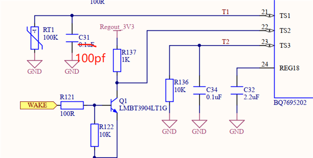
    Attached the schematic for your reference.

    Thanks

    Star

  • Hi Star,

    Your schematic seems fine. Just to confirm whether this is an issue with the ADC calculation or with the actual hardware, can you provide the raw ADC measurements from while the device is exhibiting this behavior?

    You can find the registers to get these values from Section 4.6: Subcommands 0x0075–0x0077 DASTATUS5–7(), Additional Measurements of the TRM.

    Regards,

    Max Verboncoeur

  • Hi Max

    Thanks for your help.

    When the TS1 temperature value is 128, the original value read out is 1522282 or 1523628 or 1509391 or 1510016...

    The code for TS1 ADC raw data is as follows:

    U08 BQ769x2_ReadTS1AdcRaw(S32 *value)
    {
        return BQ769x2_SubCmdResponseInt4(BQ769X2_SUBCMD_DASTATUS6, 24, value);// TS1 ADC data
    }

    U08 BQ769x2_SubCmdResponseInt4(U16 command, U08 offset, S32 *value)
    {
    U08 TX_Reg[2] = {0x00, 0x00};
    U08 buf[4];
    U08 u08Result = 0;

    //TX_Reg in little endian format
    TX_Reg[0] = command & 0xff;
    TX_Reg[1] = (command >> 8) & 0xff;

    u08Result |= I2C_WriteReg(BQ769X2_CMD_SUBCMD_LOWER, TX_Reg, 2);
    SystemTickDelay(2);
    u08Result |= I2C_ReadReg(BQ769X2_SUBCMD_DATA_START + offset, buf, 4);
    if(u08Result)
    {
    *value = (S32)(buf[0] | buf[1] << 8 | buf[2] << 16 | buf[3] << 24); // little-endian byte order
    }

    return u08Result;

    Please help check it.

    Thanks

    Star

  • Hi Star,

    It looks like the ADC is reading ~0.545V, which, assuming an ideal 18k pull-up resistor, translates to ~7.8kohms on the thermistor. Looking at your thermistor curve that's 30~31ºC, so we can be quite certain that this is not a hardware issue.

    I recommend taking a look at the example code provided on the BQ76952 product page and seeing if using those functions has any difference on the reading.

    Regards,

    Max Verboncoeur