This thread has been locked.

If you have a related question, please click the "Ask a related question" button in the top right corner. The newly created question will be automatically linked to this question.

LM3429: PSPICE for TI built-in library model appears to have problems

Part Number: LM3429
Other Parts Discussed in Thread: LM3409,

(1) PSPICE for TI program complained about the "NC" pin, so I had to connect to the node between two 976k resistors where one is connects to Vin and the other to ground (0V).

Once past that problem,

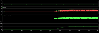
(2) The simulation (a simple Transient) gives no useful information, there is a little blip at the start and then nothing.  I have tried forcing the OVP" pin to fixed voltages above and below the threshold for over-voltage protection, but get the same result.

[History]

I was able to get useable results from simulating the LM3409 with PSPICE for TI, but the results showed me that I needed better regulation over input voltage for my LED application.  I created a new design to try using this LM3429, but have never gotten anything but grief from PSPICE.

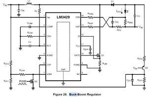
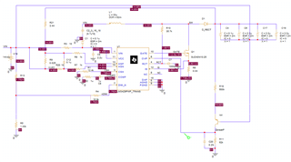
I suspect the problem is the LM3429 model: please advise. PL1_LM3429.schem.pdf

  • Mark, 

    Sorry that I could not understand the circuit you attached. Are you going to design a boost circuit, buck converter or other? What is the purpose for ROV1, ROV2 in the circuit? 

    You may refer to LM3429 PSPICE simulation circuit for design. If buck - boost is needed, you need to change OV feedback following design guide in datasheet. 

  • The topology that I am using is a buck-boost (input higher of lower than output setting) and I am essentially copying the model from that datasheet that you pasted into your response. ROV1 and ROV2 are stubs for after I get basic simulation working. I have tried an over-ride voltage above or below the threshold of "OVP" but startup fails after an initial pulse. As I did with the LM3409 model, I am running the .TRAN simulation so that I have to stop the initial calculation of bias point; the difference is that the LM3409 simulation ran fine.

    I have a suspicion that the simulation model is broken or there is some "trick" to using it.  And, I suspect this because the "NC" pin needs to be connected as shown in my initial drawing, or the simulator refuses to run. (The "NC" pin is, of course, a "no connect" pin.)

    Have you used the LM3429 model ?

  • Mark, 

    I tried your circuit with a single PNP for Vo sensing mentioned in datasheet. It shows that the model works for me.

  • I looked carefully at your simulation traces, and realized that the model started working at about 27 milliseconds.  Based my experience with the LM3409 model, I was only simulating to 200 microseconds and getting activity from essentially time=zero (and quick runtimes).  So I re-ran the simulation a few times starting with about 70 ms to make sure I did not miss anything.  As you see, in my plots, the LM3429 model starts-up for me at exactly 4.0 milliseconds. This is very strange that there is such a disparity between your start-up time and mine.  To save time, I am now running the simulations for 7 milliseconds.SimPlot-SepTraces_0-7ms.pdf

    So yes, the model sort-of works. But the LM3429 model should start-up within a few microseconds.

    Lastly, your schematic gave me a clue about the NC (no connect) pin.  I had tried to put the schematic "X" indicating a non-connected pin, but PSPICE would not tolerate that, so I had to put two very high value resistors between Vin and Ground.  That made PSPICE happy, but it was messy.  I tried your solution of just attaching a short wire stub to the NC pin, and, voila, PSPICE was happy.  This behavior is clearly not a problem with the model but a problem related to either the schematic capture or the module that extracts the circuit from the schematic.

  • 27mS is because that the COMP cap is 1uF in original circuit. If it replaced with 150nF as what you used, it will be the similar result.