This thread has been locked.

If you have a related question, please click the "Ask a related question" button in the top right corner. The newly created question will be automatically linked to this question.

BQ76952: BQ76952 help check the schematic

Part Number: BQ76952

Hi 

The customer design with BQ76952, the problem is BQ76952 needs to manually power on or off the board when the cell is under voltage protection.

Using the simulator 2.2v can charge normally, but 1.9v fails to charge. At this point, DDSG_ FET and CHG_ FET set to 1.

what causes this phenomenon?

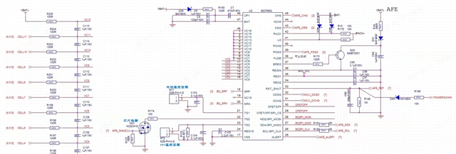
Please help check the schematic.

Thanks

Star

  • Hi Star,

    Please ensure that the customer has a cell connected across VC16 and VC15.  If VC16 is shorted to VC15, then the cell balancing switch in the top cell (between VC15 and VC14) could not be enabled, since that switch is an NFET and needs a higher voltage for its operation (it draws from BAT).  VC16 uses a PFET for its cell balancing switch, so it doesn’t need the higher voltage, but it is the only cell which uses a PFET cell balancing switch, all the rest use NFETs.

    Additionally, please make sure the VC1 capacitor is connected to GND instead of VC0.  I noticed that the cell connect portion of the schematic has 12S cells, but the BQ76952 portion of the schematic has only 6S cells connected.  is there a reason for this?

    In order to diagnose the issue, I would like to see log files of the issue, as well as the customer's gg.csv file.

    Best,

    Andria