This thread has been locked.

If you have a related question, please click the "Ask a related question" button in the top right corner. The newly created question will be automatically linked to this question.

TPS65992 does not communicate with the external device

Other Parts Discussed in Thread: TPS65992DAE, TPS65988

DEAR TI:

[TPS65992]When the DP device is inserted, it is found that the TPS65992 does not communicate with the external device through PD protocol. See the main text for details

We are using the material of your company (TPS65992DAE), and we have encountered some difficult problems and need your support!  Urgent!!


1. Background of the TPS65992DAE chip scheme;
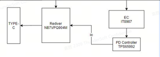
As can be seen from the above, our company replaced the original redriver chip (PS8802QFN52GTR-A3) into NB7VPQ904M chip.At present, we have two problems:

1. After replacing redriver, we find that TPS65992 cannot control Rediver chip (NB7VPQ904M) through I2C;

Q: After replacing rediver chip, do I need to update the chip firmware program of TPS65992?

Q: If you need to update the chip firmware program for the TPS65992, can you provide this firmware program to match the NB7VPQ904M?

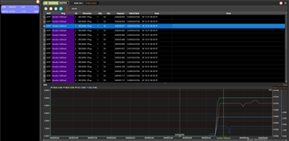
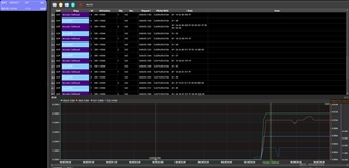
2. After we replaced the redriver, we found that TPS65992 did not have the correct PD protocol communication message when it was connected to the external DP interface device, according to our captured graphics. The message format is as follows:
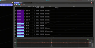
Q: We would like to confirm whether the PD protocol between DP peripherals and PD controller TPS65992 is fully controlled by TPS65992?

Q: If it is completely controlled by TPS65992, is the PD protocol captured in the figure above correct?

Q: If the PD protocol captured in the figure above is incorrect, what is the cause?How do you solve it?

3. How can I confirm that the input and output signals of the TPS65992 are normal when I insert the DP device?

  • Dear TI:

    In addition, we do not have the data of this chip, only a manual, is there any other user manual and workflow reference?

    It is our first time to design USBPD. Do you have relevant materials to learn and refer to?

  • Q: After replacing rediver chip, do I need to update the chip firmware program of TPS65992?

    Most likely yes. This is done via the I2C Events Table. I am not fully familiar with either redriver but the table is fully customizable based on connection/disconnection events and alt-mode. In the GUI go to Settings -> Show I2C Events Table

    Q: If you need to update the chip firmware program for the TPS65992, can you provide this firmware program to match the NB7VPQ904M?

    It is up to customer to update these. You can customize these as required for your redriver.

    Q: We would like to confirm whether the PD protocol between DP peripherals and PD controller TPS65992 is fully controlled by TPS65992?

    PD protocol is negotiated by us yes. The logs you show do not look correct as I do not see any power-contract negotiation. The TPS65992 may not be loaded correctly.

    Q: Read-back over I2C1 or I2C2 from the PD the Mode (0x3), Version (0xF), and Status (0x1A) registers to help further debugging.

    Q: If it is completely controlled by TPS65992, is the PD protocol captured in the figure above correct?

    It does not look correct. We see Vendor Defined messages to the plug which is expected and Vendor Defined messages to port-partner which is also expected. But no power-contract negotiation does not seem correct.

    Q: Is TPS65992 the Source or Sink?

    Q: If the PD protocol captured in the figure above is incorrect, what is the cause?How do you solve it?

    It does not look to be correct. Cause is To be determined and requires debug/information gathering. Follow initial debug steps above to gather more information.

    Q: Is issue reproducible with other DP-devices?

    3. How can I confirm that the input and output signals of the TPS65992 are normal when I insert the DP device?
    The TPS65992 PD-protocol is very straight forward. It depends on if the PD is not in an incorrect mode.

    In addition, we do not have the data of this chip, only a manual, is there any other user manual and workflow reference?

    It is our first time to design USBPD. Do you have relevant materials to learn and refer to?

    You should have access to the mySecure for TPS65992 devices and the Technical Reference Manual has the register information.

  • Hi Tsongas:

    Tsongas said:

    Q: Read-back over I2C1 or I2C2 from the PD the Mode (0x3), Version (0xF), and Status (0x1A) registers to help further debugging.

    iwan reply:
    *As you mentioned above.Can you explain in detail how to grab the steps?
    *My understanding is that I take a USB to I2C cable to read the I2C interface of the TPS65992.

      1. Send the address CMD 0x03 to enable the TPS65992 to enter the read-back mode.

      2. Send the 0x0F address command to read the version number of the TPS65992.

      3. Sendthe 0x1A address command to read the status of the TPS65992.

    *Do I understand these three steps correctly?

    *In addition, TPS65992 has many I2C interfaces, if shown, which I2C interface should I read.I think it's I2C3m

    I2C_EC_SDA

    I2C_EC_SCL

    I2C_EC_IRQ

    I2C2s_SCL

    I2C2s_IRQ

    I2C2s_SDA

    I2C3m_SDA

    I2C3m_SCL

    I2C3m_IRQ

    *Second, if the TPS65992 program needs to be changed, can I get the TPS65992 source code and TPS65992 program update related tools?
    *Can you provide debugging tools related to TPS65992?

  • Dear :

    Tsongas said:
    Q: Read-back over I2C1 or I2C2 from the PD the Mode (0x3), Version (0xF), and Status (0x1A) registers to help further debugging.
    I have read out the data of three addresses according to your requirements, please help to check the problem?

    cmd_0x0F(read 4 BYTE):4 7 9 F6
    cmd_0x03(read 20 BYTE):41 50 50 20 0 0 0 0 A3 5B DC 91 F4 EA 2E E7 AD 6 C0 1B
    cmd_0x1A(read 20 BYTE):20 0 0 0 0 0 0 0 A3 5B DC 91 F4 EA 2E E7 AD 6 C0 1B
  • Yuan,

    cmd_0x03(read 20 BYTE):41 50 50 20

    I do see PD is in APP mode: 0x41 0x50 0x50 0x20 = A P P 

    Which means the FW is loaded properly.

    cmd_0x0F(read 4 BYTE):4 7 9 F6

    Version is: F609.07.04 which is much older. We are up to F609.07.13 now. Please use the latest GUI tool to make sure you have proper setup. You can request access which will load a default configuration (with DP mode setup) from this link:

    https://www.ti.com/licreg/docs/swlicexportcontrol.tsp?form_id=302387&prod_no=TPS65992-DESIGN&ref_url=app_psil_pi

    *As you mentioned above.Can you explain in detail how to grab the steps?
    *My understanding is that I take a USB to I2C cable to read the I2C interface of the TPS65992.

    Sounds like you got this resovled based on results.

    *In addition, TPS65992 has many I2C interfaces, if shown, which I2C interface should I read.I think it's I2C3m

    No you should use I2C1 or I2C2. Once you gain access to the mySecure folder you will be able to download the specification and technical reference manual for much more detailed information.

    *Second, if the TPS65992 program needs to be changed, can I get the TPS65992 source code and TPS65992 program update related tools?
    *Can you provide debugging tools related to TPS65992?

    Program is also in the link above. Debugging tools you can use is any USB-PD protocol sniffer and I2C logic analyzer will be your best help here.

    The latest program will help avoid any old issues but I do want to point out the 0x1A read-back information:

    cmd_0x1A(read 20 BYTE):20 0 0 0 0 0

    This decodes to the only bit set is Plug Orientation = CC2 (upside-down orientation) I do not think the PD is setup to recognize the initial connection. The other device may be sending the PD messages.

    Please get latest tools and specifications, review them for some more answers like I2C reading and register descriptions.

    Thanks,

    Chris

    :

  • Dear:

    • 1. I have applied for materials according to the link you gave me;

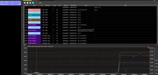
    • I used the current firmware to catch the PD protocol again, and I found that it seems to be a normal phenomenon now, as shown in the figure below:


    PD_VER:4 7 9 F6

  • Yuan,

    These all look correct from USB-PD perspective. The Power Contract is negotiated and the PD attempts to communicate to the other device via VDM messages.

    I think from this, the device is working as expected.

  • Dear  :

    I have applied for the tools and materials of PD65992DAE according to the following website, but I have not received any reply. May I ask what should I do? Our company uses your company's chips, but our chip agent has not given us any support and materials. Our design and products have come out, but at present, they are still stuck in PD65992DAE and cannot be mass-produced.

        https://www.ti.com/licreg/docs/swlicexportcontrol.tsp?form_id=302387&prod_no=TPS65992-DESIGN&ref_url=app_psil_pi

    May I ask how our company can get help from PD65992DAE?

    Thank you very much.

  • Yuan,

    Most approvers are out today and Monday. I will work with them to get you approved faster. Apologies for the delay.

    Thanks,

    Chris

  • HI :

    First of all, I'm sorry I filled in the wrong place last time, I thought it was the right place. I filled it in again this time, thank you.
    TI data team replied to my email, thank you very much. I have changed the signal of my CASE account and made sure that I changed it correctly. The URL was submitted by following the link again.

  • Hello Yuan,

    Chris is out of office today. Please expect delay in his response. 

    Thanks. 

  • HI Rohit:

    Thank you for your reply and I will continue to contact him on this issue.
      

  • HI Chris :

    I'm already getting some information on myTI/my secure . But I feel that the information is of little use to me at present,.

    right now I have one more important need.I need to drive NB7VPQ904M-D through SMBUS in TPS65992DAE. At present, the TPS65992DAE I have obtained does not have this function. Can you provide this firmware?

    Thanks.

  • Yuan,

    TPS65992DAE can support I2C control and GPIO controlled redrivers/retimers. I cannot get access to the datasheet to provide further details so I will keep the information provided general and relevant to the TPS65992DAE.

    You can use the IO Config (0x5C) register to assign GPIO events (DP Alt Mode, USB3, etc.) that can be driven as inputs to the redriver.

    You can use the I2C Events Table by clicking on top menu -> Settings -> Show I2C Controller Events Table. Then a new tab will be exposed called I2C Controller Events. You can add I2C events that will be sent by TPS over I2C3 (I2Cm) that will be sent on certain events (DP, USB, etc.)

    There are a few other registers for using the I2C Events:

    App Config Binary Indices (0x62): Used for setting ranges of events on I2C Events Table

    I2C Controller Config (0x64): Use to set the I2C Address

    Check out this App Note (pages 5 and on) for the TPS65988 which is relevant for TPS65992DAE: https://www.ti.com/lit/pdf/slvae18

  • MY friend:

    I think I'm in trouble again;

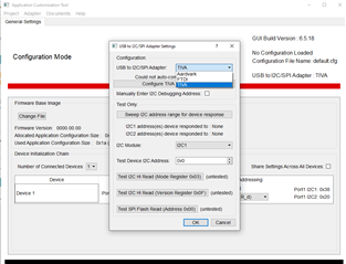
    1. First, I got the GUI tool of your company, but now I want to use the USB 2 I2C tool to connect to the I2C1 of TPS65992DA, but the tool displays that the connection cannot be made. Drive the one I already installed.

    -- Can you tell me what mode of connection I should choose?


    2. Some of our PD chips were good in the morning, but suddenly they could not be used in the afternoon. We measured that there was no PD signal, how should we analyze this problem?

    3. When PD is normal, we insert a DP display screen, and at this time PD will give a high state of HPDS to EC, which is correct. However, after I pulled out the DP display cable, the HPDS signal from PD was still high, which was incorrect. May I ask how I should analyze this problem?

    I'm always online, my friend.

  • Chris is out of office this week. He will be back in office next week.

    There are only the adapter devices we support TIVA, Ardvark and FTDI. I am not familiar with USB2-I2C.

  • Yuan,

    For issue 1, Our tool does not support USB2-I2C. You can use it to communicate and read/write data to PD. But built-in support for GUI is TIVA/FTDI

    Issue 2: The best way to tell if a PD is alive is to measure LDO_3V3. This will be at 3.3V if we are receiving power from VBUS or VIN_3V3

    Issue 3: I am not as familiar with HPD signal characteristics as I am the function. Is it supposed to be a push/pull? Open-drain? These answers will help understand if the issue is a physical issue.

    Thanks,

    Chris

  • Dear :

    Issue 3: I am not as familiar with HPD signal characteristics as I am the function. Is it supposed to be a push/pull? Open-drain? These answers will help understand if the issue is a physical issue.

    ==================

    It is the value of PD chip that our EC chip reads through SMBUS. We don't know about PD chips here. I don't think this is a pin foot.

    Or do you mean that PD chip has a pin that can reflect the HPDS state?


  • In addition, if I want to connect my board through your APP TOOL, should I buy your connector? As you say below.

    For issue 1, Our tool does not support USB2-I2C. You can use it to communicate and read/write data to PD. But built-in support for GUI is TIVA/FTDI

  • Yuan,

    It is the value of PD chip that our EC chip reads through SMBUS

    I think you are talking about what we call 'Virtual HPD' signal from PD. Is the EC reading register 0x5F (Data Status) to get the HPD_Level signal?

    Your previous post made it sound like you were using a GPIO which would be 'Physical HPD' signal.

    if I want to connect my board through your APP TOOL

    If you have your EVM, you can use the TIVA on-board.

    Thanks,

    Chris

  • HI :

    I think you are talking about what we call 'Virtual HPD' signal from PD. Is the EC reading register 0x5F (Data Status) to get the HPD_Level signal?
    yes,it's 'Virtual HPD' .This value is read by EC through I2c, which is another new problem we found.

    The problem is described as follows:

    When we insert DP, DP works;

    Then we pull out the DP and insert the USB flash drive, and the USB flash drive is not recognized.

    Our own analysis:

    We find that after DP is inserted, PD will pass an HPDS value to EC, and this HPDS is high when DP is inserted. However, after removing DP, the HPDS is still high. This may still be nothing unusual. But when we insert the USB flash drive, this HPDS value should be low, right? But in fact, when you insert the USB flash drive, the HPDS is still high.

    We currently do not have EVM, so we do not know how to analyze this problem. Please tell us the analysis method, thank you。


  • Yuan,

    What you will need to look at next would be the number of HPD_High signals coming from PD logs compared to the I2C IRQ events read-back of the Data Status (0x5F) register. You should see equal number of IRQ assertions for the HPD_High bit in the Data Status as you do HPD_High signals from the PD-side.

    Thanks,

    Chris

  • HI :

    I have 3 new questions:

    1. When PD supplies power to type-c devices such as USB-HUB, does PD have any limitation on discharge current or voltage?

    2. Our current hardware does not support the PD fast charge function, can we turn off the PD fast charge protocol through EC? If so, how should we set the register?

    3. If we turn off the PD fast charge protocol according to 2, will it affect our DP and other functions?

  • Dear Chris:

    I have three USB-HUB devices, one of which has many interfaces. I connected this HUB device to the board we designed. I found that PP5V of TPS65992DAE was normal, but CC1/CC2 and VBUS had no voltage. Other HUB devices of different models are normal, and Qualcomm's reference machine is also normal. Why is that?

  • 1. When PD supplies power to type-c devices such as USB-HUB, does PD have any limitation on discharge current or voltage?

    PD is only limited by the Transmit Source Capability and Transmit Sink Capability registers

    2. Our current hardware does not support the PD fast charge function, can we turn off the PD fast charge protocol through EC? If so, how should we set the register?

    I do not know the definition of PD Fast Charge. You can limit the current/voltage by changing the Transmit Source/Sink registers.

    3. If we turn off the PD fast charge protocol according to 2, will it affect our DP and other functions?

    Depends on device but typically no.

    Why is that?

    I have been given limited information so can only make assumptions. considering other HUB devices work well, the one that does not work may be a device issue not a PD issue.