Hi.
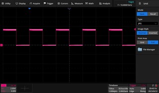
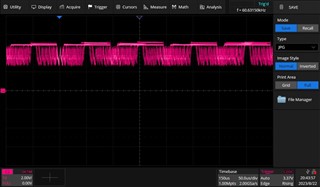
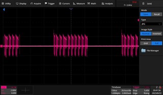
I'm testing a PCB that acts like a braking resistor circuit (https://images.app.goo.gl/hzKZzQpF1cWaBLFaA). I'm using this low-side gate driver to switch the GaNFET EPC2215. I'm using a square signal waveform of 10kHz and 3.3V unipolar signal. But the output signal have a very strange waveform. I attach you the waveforms in the different pins:
Pin 1: VDD (12V)

Pin 3 (Non-inverting input):

Pin 6 (VREF):

Pin 5 (OUT):


As you can see, the switching at the output is wrong.
I'll attach you also the schematic capture of the driver and the MOSFET.


