This thread has been locked.

If you have a related question, please click the "Ask a related question" button in the top right corner. The newly created question will be automatically linked to this question.

BQ27Z746: BQ27Z746 Protector calibration data

Part Number: BQ27Z746
Other Parts Discussed in Thread: BQSTUDIO

Hi

I have a query need your help.

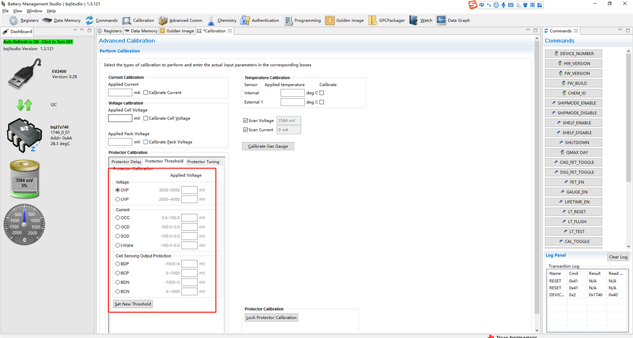
The calibration values marked by the red line are not stored in the Data memory. In actual production, it is impossible for every product to do this calibration.

How can I save the protector calibration of this part in the golden image.

Waiting for your reply.

Thanks

Star

  • Hi Star,

    The data memory value does not affect the actual value of the protection set, there is a separate secure memory location for the protection that is not apart of the golden image files and needs to be added.

    There are 2 options, they can calibrate each gauge in production with a reference voltage for high accuracy, or they can use the protector tuning function for lower accuracy but can just write to the register in production instead of needing a reference voltage.

    Sounds like they need option 2 which is using the protector tuning. To use this option they need to have a new gauge and set the protection values desired via the protector tuning method. They can not use a gauge that has previously been set using protector threshold. They can then read these values out via register F0A2, this can be done with Advanced Comm in BQStudio.

    I2C address: AA

    Starting register: 3E

    A2 F0 write then read

    They will get something like this:

    A2 F0 01 00 0E 23 20 08 08 08 09 08 5F 5F 43 5B 32 04 5B 5C 5B 5C 08 08 10 17 07 08 09 11 09 11 00 00 78 22

    The bolded values are the actual protection values set on the gauge bytes 10~19

    In production they need to write only these values to all gauges. Its very important to only write bytes 10~19 and to not corrupt the surrounding reserved bytes

  •  

    HI  

          The data obtained after writing and reading according to your method is 54 00 06 81 40 00 00 00 00 00 00 00 00 00 00 00 00 00 00 00 00 00 00 00 00 00 00 00 00 00 00 00 00 00 E4 08。Did I do something wrong?Do you have instructions on how to write protected values?Which byte does each protected value correspond to?

  • Hello,

    Please ensure that auto update and scan are both turned off when using advanced comm plugin, these can interfere with results.

  • HI Hayes 

                 1、 What format of golden image can I save the modified values in through protect tuning?Do I have to use the advanced comm plugin to write?


                2、Auto update and scan are both turned off ,the data is still wrong.

  • Hello,

    1.Unfortunately the protection settings are not saved in any golden image file. The I2C commands can be added into a bq.fs file or parsed into the production environment

    2. Please ensure gauge is also in calibration mode, in command window can send CAL_TOGGLE command. CAL_EN bit will be set high when gauge is in calibration mode.

  • HI

       Thank you for solving my problem,I can get the right data。

        A2 F0 01 00 11 28 20 08 08 08 09 08 27 10 0C 5B 2E 04 5B 5C 5B 5C 08 08 10 17 07 08 09 11 09 11 00 00 32 22

        27 10 0C 5B 2E 04 5B 5C 5B 5C 

        Is there a formula for converting these hexadecimal data into protected values?

  • Hello,

    The hexadecimal data doesn't correlate directly to raw IVT values, but step values in the protection itself that then determine the IVT protection value. After setting the value with protection tuning in BQStudio you can then read this same data out to get the correct protections.