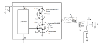
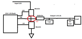
Hi,
This thread has been locked.
If you have a related question, please click the "Ask a related question" button in the top right corner. The newly created question will be automatically linked to this question.
Hi,
Hello,
Is 90% your assumption for your calculations? Or is it based on measurements?
The measurement leads to a higher efficiency.
Can you please clarify your question?
Thanks,
Calan
Hello,
Your question is not very clear, but i am assuming you are asking about the power losses between the inductor and MOSFT. the power losses can be estimated as I2R where R for the MOSFET is the RDSON and the inductor is DCR. This is very simplistic as much more losses are is contributing the efficiency and losses
The following factors can contribute to power loss:
1. Conduction loss caused by the on-resistance of the MOSFET
2. Switching-loss in the MOSFET
3. Reverse recovery loss in the body diode ܲ
4. Output capacitance loss in the MOSFET
5. Dead time loss ܲ
6. Gate charge loss in the MOSFET ܲ
7. Operation loss caused by the IC control circuit
8. Conduction loss in the inductor ܲ
9. Loss in the capacitor
Thanks
Tahar
Hi,
The above is from calculation depends on load and efficieny of the convertor. The above calculations is just for reference and my question is generic that what will be the current value between switching mosfet and inductor.
Hello Selvaprasad,
Your question is not very clear. Please go over these application notes, it will give you some basic understanding on how buck works, hopefully it will answer your question. If not, please elaborate more so I can understand what are you looking for so I can help you better.
https://www.ti.com/lit/an/slva057/slva057.pdf?ts=1692891638495
Thanks!
Tahar
Hi,
Thanks, I have added a example image , so that it will be easy to understand.
As per image, the input voltage is 12V and Output voltage is 3.3V with 2A.
Consider Buck convertor efficiency is 100%, so Pi=Pout, then Iin= (3.3*2)/12 = 0.5A
Till now, input current is 0.5A, output current is 2A, so what will be the current between the input and output, means between the mosfet and inductor.
I have marked it in red colour. Whether it will be same as input current or output current.
Also, for PI simulation whether we need to consider the inductor as source or mosfet/buck convertor output pin as source.
Thanks,
Hello,
The current on the red circle is called Inductor current that will be charging up when the High Side FET is ON and going down when the Low Side FET is ON.
this application note will help you,
https://www.ti.com/lit/an/slva057/slva057.pdf?ts=1693427433242
https://www.youtube.com/watch?v=tMJRwq8CWeI
Thanks
Tahar