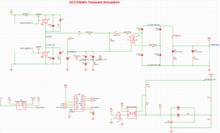
I am designing an LLC DC-DC converter using the UCC256403. Input voltage of 13.6V nominal with a 500V output.
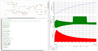
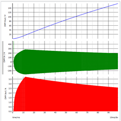
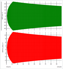
When I run the Simplis simulation, I'm getting very high input currents from my DC source and values at Isns that are way above the 4V threshold. I included some snapshots below. I also included my command window values below.
Does the UCC25640x Simplis model have OCP capability? It seems like when I try to adjust the values of Cisns and Risns, it has no change on my outputs. With the current values listed below, I should see a pk-pk on Vcr of ~4V and a peak of 12A @ OCP1 when Visns hits 4V. However, you can see from the figures below that we are nowhere close to those values.
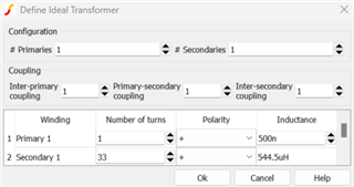
Another question: in the example provided, there are two inductors to emulate the leakage inductance and a separate inductance for the magnetizing inductance. In my model, I went to 1 inductor for the leakage inductance and integrated the magnetizing inductance into the transformer model as the primary side inductance. Is there any reason this shouldn't work?
Thank you in advance for the help, and please let me know if I need to provide more information.
.simulator SIMPLIS
*.ac DEC 100 10 100k
+ NODE_V
.options
+ PSP_NPT=2
+ POP_ITRMAX=200
+ POP_USE_TRAN_SNAPSHOT
+ POP_OUTPUT_CYCLES=5
+ SNAPSHOT_INTVL=0
+ MIN_AVG_TOPOLOGY_DUR=1a
+ AVG_TOPOLOGY_DUR_MEASUREMENT_WINDOW=128
*.pop TRIG_GATE={TRIG_GATE} TRIG_COND=0_TO_1 MAX_PERIOD=15u CONVERGENCE=1p CYCLES_BEFORE_LAUNCH=1000 TD_RUN_AFTER_POP_FAILS=0
.tran 1 0
.globalvar IC_ID=3;
*Input DC voltage
.var Vin0 = 13.6
* Output initial DC current
.var I0 = 0
* Output DC current after pulse change
.var I1 = 0
* Output curent change pulse duration
.var Tw = 10m
* Output curent change delay time
.var Td = 25m
* Output current rising and falling time
.var Tr_I = 10n
* Power MOSFET Equivalent drain-to-source capacitance
.var Cds = 160p
* Power MOSFET RDson
.var Rdson = 0.014
* Deadtime
.globalvar TD1 = 400n
.globalvar TD2 = 400n
* Transformer parameters
* Please direct input the transformer turn ratio into the transformer model in the schematic (TX1)
* Resonant tank info
* Resonant inductor
.var Lr1 = 500n
.var Lr2 = 35u
* Magnetizing inductor
.var Lmag = 2u
.var Lleak = 0.54u
* Resonant capacitor
.var Cr = 4.5u
* Output capacitor
* Electrolytic capacitor
.var COUT = {1200u}
.var esr = {5m}
* Ceramic capacitor
.var Ccer = {0.1u}
.var esrcer = {1m}
* BW Pin resistor
.var RBW = 4.64k
* Soft start capacitor
.var CSS = 60n
* Soft start initial voltage
.var Vssinit = 0.30
* Burst mode threshold
.globalvar BMTH = 0.6
* VCR capacitor divider
.var Cupper = {820p}
.var Clower = {8200p}
* ISNS differentiator
.var Cisns= {10000p}
.var Risns=150
* Optocoupler CTR
.var CTR=220m;