This thread has been locked.

If you have a related question, please click the "Ask a related question" button in the top right corner. The newly created question will be automatically linked to this question.

UCC27710: UCC27710 test failure on fixed location of the board

Part Number: UCC27710

Dear team,

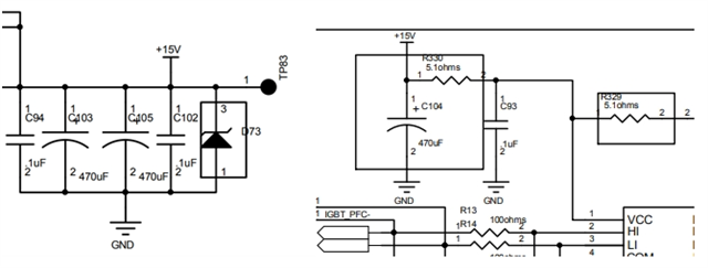
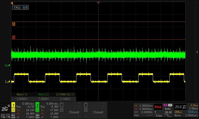
my customer is using UCC27710 on multi locations on a 3kw UPS circuit and a failure occurred on the same position of the board. I have complete the FA report and add some test waveforms for the system. Would you please take a look into this? TI UCC27710 FAR Form-INVT.xlsx

  • Hello team, 

    Can anyone have further questions about this case? So I can update to the customer in cae we can provide any advice.

    Thanks for your support!

  • Hey Zoe,

    Thank you for your question!

    Based on the schematic, there is a 47uF bootstrap capacitor in place and only a 0.1uF capacitor on VDD. Is there an additional capacitance on VDD as the VDD capacitance is supposed to be at least 10 times greater than the bootstrap capacitance?

    Also, can you check the IC with a voltmeter from LO to COM and compare that with a known good device? Please also confirm that all voltages are within the recommended operating range of the device.

    To provide further feedback, the waveform plot of the LO driver output from a working unit would be appreciated as well.

    Thank you,

    William

  • William,

    Thanks for the reply! 

    1.VDD is powered by 15V and has two 470uF capacitor in parallel close to it. There is also a 470uF capacitor near to the driver.

    2.The test results of the multimeter are as follows, for LO output:


    pin-pin

    Voltage drop + impedance

    low-side output

    45

    Good IC 0.54V+344kΩ,abnormal IC0.54V+348kΩ

    54

    Good 2.0V+1MΩ, abnormal 1.5V+263kΩ

    51

    Good 0.43V+210kΩ,abnormal 0.43V+210kΩ

    15

    Good 1.5MΩ,abnormal 404kΩ

    3.The output of the LO driver is abnormal. The theoretical output is 15V and the actual output is about 2V. The waveform is as follows:
    CH1: LI input waveform CH2: LO output waveform

    Any further information, please let me know. Thanks!

  • Hey Zoe,

    I have a few follow up questions for this.

    1. When the driver failed, did the IGBT fail also? Or did any other devices such as the gate resistors or diode fail?

    2. What are the part numbers for the IGBT and the turn off diode on the gate?

    3. What temperature is this failure happening at?

    4. Is this a steady state failure or is this during a start-up or transient?

    5. Can you take some scope captures of the start-up and steady state LO and HS measured at the pins of the driver and also measured at the IGBTs? Measuring LO to ground at driver and Gate to Emitter of the Low Side IGBT.

    6. If you swap the driver out for a new part, does it work normally?

    7. Can you measure the voltage of the VDD supply at the power supply and at the driver pins as well?

    8. The 470uF CVDD capacitor you are referring to near the driver is not shown on the layout snip that was sent to me, can you send a snip that includes that as well?

    9. Are you able to swap the 47kOhm pull down resistor for a 10kOhm? The 47kOhm is probably too high for this application.

    Let me know if you have any questions.

    Thank you,

    William Moore

  • 1. When the driver failed, did the IGBT fail also? Or did any other devices such as the gate resistors or diode fail? 

    ---Only gate driver failed.

    2. What are the part numbers for the IGBT and the turn off diode on the gate?

    ---DGW10N65CTH,10A 650V

    3. What temperature is this failure happening at?

    ---Ambient temperature 30°

    4. Is this a steady state failure or is this during a start-up or transient?

    ---Steady state

    5. Can you take some scope captures of the start-up and steady state LO and HS measured at the pins of the driver and also measured at the IGBTs? Measuring LO to ground at driver and Gate to Emitter of the Low Side IGBT.

    ---LO abnormal output 2V. Other signals are normal.

    6. If you swap the driver out for a new part, does it work normally?

    ---Yes.

    7. Can you measure the voltage of the VDD supply at the power supply and at the driver pins as well?

    ---Gate driver and VDD supplies are the same. Measured around 15.4V.

  • 8. The 470uF CVDD capacitor you are referring to near the driver is not shown on the layout snip that was sent to me, can you send a snip that includes that as well?

    ---470uF capacitor is used as energy storage+filter, is far away from failed gate driver.

    9. Are you able to swap the 47kOhm pull down resistor for a 10kOhm? The 47kOhm is probably too high for this application.

    ---Replace the damaged IC will cover the failed situation, thus based on replaced IC swap resistance is not meaningful for them. 

    Looking forward to your reply! Thanks!

  • Hey Zoe,


    Thank you for this response with all of this information.

    One of the most important things is having the bypass capacitor near the driver and approximately 10 times that of the bootstrap capacitor. Without that, there can be excessive noise and spikes on these pins which would cause damage. Check out the Bootstrap Circuitry Selection for Half-Bridge Configurations document for some more information this at this Link

    How many failures have been seen like this? Is this a consistent problem where you set up a board with the device and it fails and is replaced and works after that?

    Could you test this on about 5 devices and boards and see if they can make those fail in the same way? If so, put another bypass capacitor as close to 470uF as you can get, place it right on top of driver and repeat this test on the same boards and configurations and see if that fixes it.

    Let me know if you have any further questions.

    Thank you,

    William Moore

  • Hey Zoe,

    Were you able to solve this? If so, could you share your findings?

    Thank you,

    William Moore

  • Hey Zoe,

    I am going to close this thread with the assumption that this has been resolved. If if has, I would be interested to know what you found and what the solution was. If it has not been solved, please let me know and let me know if you have further questions.

    Thank you,
    William Moore