- Ask a related questionWhat is a related question?A related question is a question created from another question. When the related question is created, it will be automatically linked to the original question.
This thread has been locked.
If you have a related question, please click the "Ask a related question" button in the top right corner. The newly created question will be automatically linked to this question.
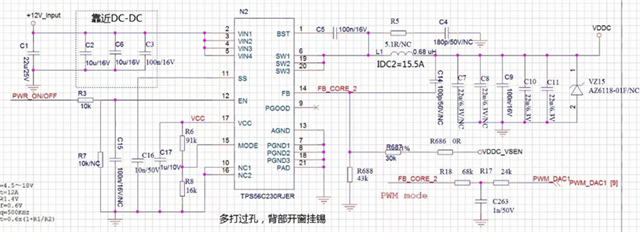
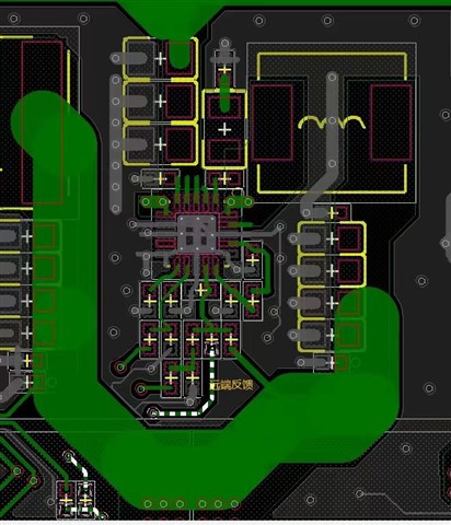
The TPS56C230 on the customer's board has a double pulse problem, the following is the schematic diagram and PCB diagram.


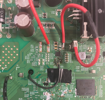
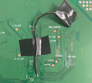
The customer's remote feedback wiring is a long line with a via hole. I cut the PCB line and passed the flying line, as shown in the figure below, and found that the double pulse problem was cancelled.

The double pulse problem should be caused by the sensitivity of the FB through investigation, so is there any problem when designing the chip? Or do you have to pay attention when using it?
Hi Qingze,
It is likely the remote sense line layout is introducing noise since the flying wire connection works as expected. I shared some information via email on this to you today and would be best if you can try to get the project layout files to look at this a bit better. We are discussing via email on this so let us continue there. If we find a resolution, I will post it here.
Thanks,
Amod