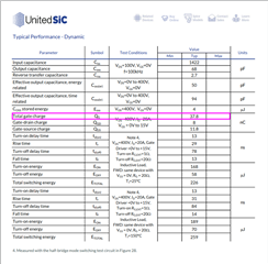
Part Number: TPSI3050
Hi,
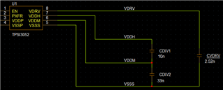
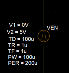
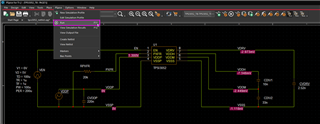
I'm considering TPSI3050 to use as a SSR as a switch to send AC sine signals.
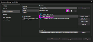
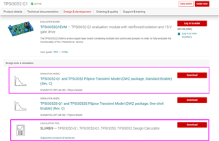
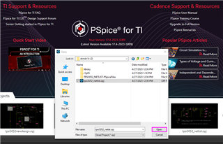
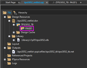
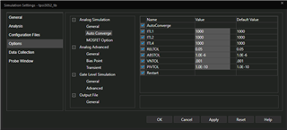
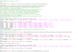
I want to simulate TPSI3050 from SLVMDL0F.ZIP downloaded from TI website with Orcad capture version 17.2 2016 but when I lauch the simulation I get several errors as shown below:
**** RESUMING tpsi3050_tb.cir ****
.END
INFO(ORPSIM-15423): Unable to find index file tpsi3050.ind for library file tpsi3050.lib.
INFO(ORPSIM-15422): Making new index file tpsi3050.ind for library file tpsi3050.lib.
*****************************************************************************
* (C) Copyright 2023 Texas Instruments Incorporated. All rights reserved.
* TI Confidential - Selective Disclosure
*****************************************************************************
** This model is designed as an aid for customers of Texas Instruments.
** TI and its licensors and suppliers make no warranties, either expressed
** or implied, with respect to this model, including the warranties of
** merchantability or fitness for a particular purpose. The model is
** provided solely on an "as is" basis. The entire risk as to its quality
** and performance is with the customer
*****************************************************************************
* PSpice Model Editor - Version 17.4.0
*$
.SUBCKT MODE_SEL_FUNC DUTY SEL0 SEL1 SEL2 SEL3 SEL4 SEL5 SEL6 VSSP
E_SEL0 SEL0 0 VALUE = {IF ( ((V(DUTY)-V(VSSP)) < 532mV & (V(DUTY)-V(VSSP))>= 253mV) | ((V(DUTY)-V(VSSP)) < 253mV) |((V(DUTY)-V(V
$
ERROR(ORPSIM-16366): Line too long. Limit is 132 characters.
E_SEL1 SEL1 0 VALUE = {IF ( (V(DUTY)-V(VSSP)) < 652mV & (V(DUTY)-V(VSSP)) >= 532mV, 3.5, 0)}
E_SEL2 SEL2 0 VALUE = {IF ( (V(DUTY)-V(VSSP)) < 770mV & (V(DUTY)-V(VSSP)) >= 652mV , 3.5, 0)}
E_SEL3 SEL3 0 VALUE = {IF ( (V(DUTY)-V(VSSP)) < 888mV & (V(DUTY)-V(VSSP)) >= 770mV, 3.5, 0)}
E_SEL4 SEL4 0 VALUE = {IF ( (V(DUTY)-V(VSSP)) < 1.014V & (V(DUTY)-V(VSSP)) >= 888mV, 3.5, 0)}
E_SEL5 SEL5 0 VALUE = {IF ( (V(DUTY)-V(VSSP)) < 1.183V & (V(DUTY)-V(VSSP)) >= 1.014V, 3.5, 0)}
E_SEL6 SEL6 0 VALUE = {IF ( (V(DUTY)-V(VSSP)) < 1.665V & (V(DUTY)-V(VSSP)) >= 1.183V, 3.5, 0)}
.ENDS MODE_SEL_FUNC
***********************************************************************************
* PSpice Model Editor - Version 17.4.0
*$
.SUBCKT MODE_SELECT VSSP VDDP OOK 2PIN_MODE EN2PIN RESETZ SEL0 SEL1 SEL2 SEL3 SEL4 SEL5 SEL6 SELQ0 SELQ1 SELQ2 SELQ3 SELQ4 SELQ5 SELQ
$
ERROR(ORPSIM-16366): Line too long. Limit is 132 characters.
E_TON TON VSSP VALUE = { IF (V(SEL0) > 0.5V, 140.8mV, IF (V(SEL1) > 0.5V, 300.8mV, IF (V(SEL2) > 0.5V, 460.8mV,
+ IF (V(SEL3) > 0.5V, 620.8mV, IF (V(SEL4) > 0.5V, 780.8mV, IF (V(SEL5) > 0.5V, 920.8mV, IF (V(SEL6) > 0.5V, 1080.8mV, 0V)))))))}
G_IEN IEN VDDP VALUE = { IF (((V(EN2PIN) > 0.5V) & (V(OOK) < 0.5V) & (V(RESETZ)-V(VSSP) > 0.5V)), (IF (V(SELQ0) > 0.5V, 1.9mA,
$
ERROR(ORPSIM-16366): Line too long. Limit is 132 characters.
+ IF (V(SELQ2) > 0.5V, 4.0mA, IF (V(SELQ3) > 0.5V, 5.0mA, IF (V(SELQ4) > 0.5V, 6.0mA, IF (V(SELQ5) > 0.5V, 7.0mA, IF (V(SELQ6) > 0.5
$
ERROR(ORPSIM-16366): Line too long. Limit is 132 characters.
Index has 71 entries from 1 file(s).
.SUBCKT MODE_SEL_FUNC DUTY SEL0 SEL1 SEL2 SEL3 SEL4 SEL5 SEL6 VSSP
E_SEL0 SEL0 0 VALUE = {IF ( ((V(DUTY)-V(VSSP)) < 532mV & (V(DUTY)-V(VSSP))>= 253mV) | ((V(DUTY)-V(VSSP)) < 253mV) |((V(DUTY)-V(V
$
ERROR(ORPSIM-16366): Line too long. Limit is 132 characters.
ERROR(ORPSIM-15108): Subcircuit MODE_SELECT used by X_U1.X_U1_UPRIM_UMODE_U285 is undefined
Please, could you explain how can I simulate with the library downloaded from TI? Should I modify something from the library?
Thank you in advance