This thread has been locked.

If you have a related question, please click the "Ask a related question" button in the top right corner. The newly created question will be automatically linked to this question.

BQ51013B: Intermittent power transfer

Part Number: BQ51013B

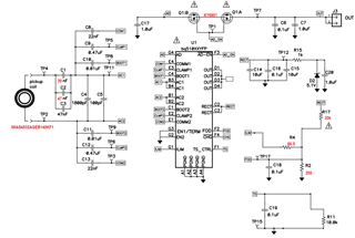
I'm trying to develop a wireless charging solution using the BQ51013B chip. My schematic is similar to the example design with a few simplifications/changes (schematic attached):

  1. For testing I'm using a 10k resistor as the TS
  2. EN1 and EN2 are connected to ground
  3. The coil is IWAS4532AGEB140KF1 (Ls = 14.1)
  4. C1/C2/C3 are 37nF/47nF/47nF

My load is just an LED connected by a 330 Ohm resistor.

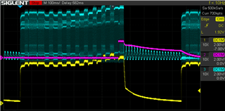
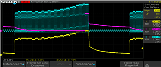
My problem is that the power transfer is intermittent - it's on for about 0.1s and then off. This cycle repeats every 1s. I'm attaching the result from probing the circuit. The traces are:

  1. Yellow (1) is RECT
  2. Pink (2) is OUT
  3. Blue (3) is AC1


I would appriciate any help.

Thank you

  • Hi

    Something is going wrong when the output is turned on, We see out go high and TX shut down, suspect the RX is sending an End Power Transfer. We see a packet just before TX turns off.

    Other thing we see is the voltage does not reach 5V looks like about 2V.

    Double check the 10k resistor connected to TS pin?

    Double check the output load, can the USB input power the load?

  • Sorry, I realized that OUT was connected after the resistor, I'm attaching a new picture with correct OUT.

    I made sure that the 10k TS resistor is connected. When I take it out the circiut stops working completely. It also doesn't work with 5k resistor, with 20k the behavior is the same as with 10k.

    With USB connected (VBUS to AD), the diode is consistently on.

    Thank you

  • OK that looks a little better.  We still have the shutdown when OUT turns on.

    Couple of things to try:

    1.) Capacitor across the TS / CTRL 10k resistor, reduce to 0.01uF or 0.001uF (for test can remove).

    2.) ILIM may be an issue, check the votlage at ILIM pin at turn on should be below 1.2V.

    3.) Double check EN1 / EN2 connection and AD voltage.

    I think something is causing RX to send shutdown command to TX when OUT turn on.  TS is usual suspect in this case, also that is when current starts to flow in ILIM circuit.  May also have some path for OUT voltage to get to AD which would cause shutdown.

    1. I tried both no cap and 1nF cap on the TS/CTRL pin and there is no change with both.
    2. ILIM looks to be around 50mV consistently.
    3. Rechecked EN1/EN2 - both are connected to ground. 

    But you were right on your last point! I did have a path from the OUT to AD which was causing the shutdown - it was just me incorrectly using the double mosfet...

    Thanks a lot for your help, I really appriciate it!