This thread has been locked.

If you have a related question, please click the "Ask a related question" button in the top right corner. The newly created question will be automatically linked to this question.

TPS63805: Shifting the switchmode frequency up (above the audible region) during low current operation

Part Number: TPS63805

We have designed TI’s TPS63805 “Buck/Boost” Switchmode Power Supply IC into one of our battery-powered (uses 2 AAA alkaline batteries) headsets.

The issue we are having is that in low power conditions (approximately 10mA) we are getting a high-pitch audible tone in our earpiece.  It appears that the TPS63805 switching frequency is the root cause of this tone.

We did not foresee this condition when we first designed the product, but as a corrective action we are looking for ways to shift the switching rate to a higher frequency that is above the audible range (20Khz or higher).

One obvious way to try to shift the frequency up is to increase the load, but our headset is battery powered and doubling the current would result in a drastic degradation on the usable life of the battery/product.

We have started to experiment with ways to alter the feedback loop to “trick” the IC into switching at a faster rate.    One way we found to do this is to introduce a parallel capacitor on one of the resistors in the resistor-divider feedback loop.  Our concern with doing this is whether the TPS63805 will remain stable under all operating conditions with the introduction of this capacitor.   We are looking for TI’s help to understand the impact of this addition capacitor – for example there may be a range of acceptable capacitor values that we may need to stay within.  

In the end, our goal is to shift the frequency above the audible range without loss of battery life.  Can TI provide advice?  Perhaps there are other ways to accomplish this goal?

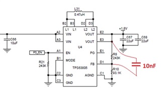
Below is an excerpt of our schematic showing the circuitry surrounding the TPS63805.

We are experimenting by putting a parallel capacitor (10nF) across R8 (as shown in the schematic excerpt below).  What we don’t know is whether we are unintentionally violating the performance/stability of the switcher by making this addition/change.


  • Hi Knych,

    Good idea to add a Cff to increase the switching frequency in light load, yes it will works.

    10nF is too big one and the zero and pole introduced into loop is lower than cross, so yes, it will bring risks of loop instable. our recommend  one is smaller than 10pF.

    Check loop  with a transient test is tricky and helpful way. conditions below.

    • boost mode
    • maximum output current in your application
    • FPWM mode or just PFM mode, but start with a load which can make sure device work in PWM

    Regards

    Tao

  • Hi Tao,

    Thanks for your reply.  Just to let you know that we do not run the TPS63805 at very high current.  Our maximum demand on the part is 80mA.  As a result, we likely never run it in PWM mode.    

    Based on our 80mA maximum, do you still think that 10nF is too large?   

    We are presently testing both the 10nF and 100pF options concurrently so that we can see stability & performance under various conditions (low battery, temperature extremes, various load conditions).    

    BTW - Do you work for TI (Designer or FAE) or are you an expert user of the TPS63805?   

    Appreciate your input and willingness to help,

    Bernie

  • Hi  Bernie,

    I am system and application engineer from Ti. 

    Since 80mA is the maximum load in your application, i think 10nF is acceptable.

    Regards

    Tao

  • Hi Tao,

    Your advice on the capacitor has been very helpful, we are cautiously optimistic that we will likely go forward with the smaller 100pF capacitor as it seems "safer" (for stability), but we are not done yet with all of our testing.   

    In the meantime, we are exploring another potential approach to shifting the switching frequency above the audible range.  This 2nd approach is to reduce the inductor value from 0.47uH to 0.22uH (reference our schematic above).   Do you have any thoughts/recommendation about going to this smaller inductor value?

    At this point an inductor value change is our back-up approach, but it has some advantage for us because we would not have to change our printed circuit board layout if we simply make a value change.  The 100pF capacitor approach requires us to add pads for a new/additional component (new PCB layout).

    Thanks again for your time and advice,

    Bernie

  • Hi Bernie,

    Thanks again for your time and advice,

    My pleasure and you are welcome. Change the inductor has impact at frequency of RHPZ, but since device always work in PFM mode, no cooncern of loop stability. i think it is ok too.GrinningGrinning

    Be carefull about the variation of inductance, it will change the actual switching frequency. Just do it with some margin. 30% margin of frequency should be reasonable. thanks

    Regards

    Tao