This thread has been locked.

If you have a related question, please click the "Ask a related question" button in the top right corner. The newly created question will be automatically linked to this question.

UC3842: Ramp compensation & strange behaviour on UC3842

Part Number: UC3842
Other Parts Discussed in Thread: UC3845, UC3843

We are building an MPPT tracker using the UC384* Family.

The tracker takes a voltage from 100V to 300V and outputs constant current with a voltage limit of 350V. The current is regulated at the primary side (10A peak), so naturally the output will vary based on the available current and voltage.

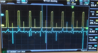
The circuit seems to work well, but I want to increase the switching frequency to some 50Khz. Whenever I go past around 10Khz, I start to have a pulse starting and stopping shortly after or some sort of jitter that increases the Mosfet temperature. I tried to clamp the sense voltage feedback, thinking it could be noise, but the problem persists.
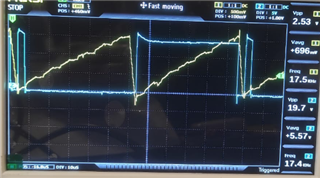
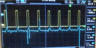
Here we can see the gate signal (blue) and the oscillator ramp (yellow).
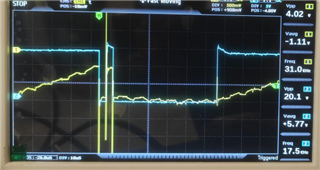
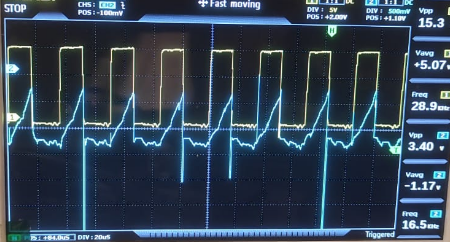
Here we see the gate signal and the inductor current.

I believe that this is some problem with the compensation. Swapping to a UC3845 resolves the strange pulse behaviour, but naturally I am limited to 50% duty. It also only seems to do full width pulses, skipping when necessary, instead of reducing the duty cycle.
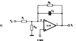
I'm using the following compensation scheme with C = 100pF and R = 150K

I have also tried to use the power stage designer tool, but seems more suited to offline converters? Or perhaps I'm not fully sure what to look out for!

  • I removed all the compensation and manually connected the COMP pin to a variable voltage source, to replicate a soft start, based on the peak current.

    Again with the UC3845, I was able to adjust the duty cycle, as expected

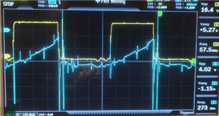
    With the UC3843, It continues to skip every other pulse, just after the start. I'm at a loss on why if behaves this way!

    Close up:

    There seems to be a large reverse current at turn off and again at turn on/off which isn't seem on the net cycle. Can only imagine this would be because the current on the inductor hasn't yet fallen to zero. Both the Diode and Mosfet are SiC, so I am not expecting reverse leakage to be part of the problem.

  • Hi,

    Please provide your schematics for review.

  • The issue is resolved - It was caused by the cycle to cycle current limitation, when following pulse started before the inductor had enough time to fully discharge (seen at high duty cycles)

    Reducing the inductor size allowed me to go well into 50+KHz, where if the pulses are to close the same behaviour repeats. It seems the UC3845 worked well, as the duty cycle limitation, naturally forces the inductor to fully discharge before the start of the following pulse.