This thread has been locked.

If you have a related question, please click the "Ask a related question" button in the top right corner. The newly created question will be automatically linked to this question.

BQ76940: BQ76940

Part Number: BQ76940

Hello,

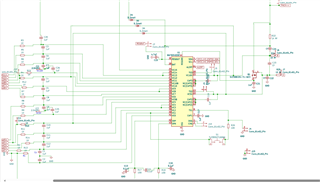
i am using BQ76940 to measure voltages of series of 12 cells (only voltage measurement), i've used reference design given in the datasheet.

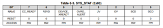
then after connecting everything. i was able to read all cell voltages with good accuracy. i repeated the task while discharging the batteries. but when i started charging, for couple of minutes i was getting cell voltages, after that every parameter becomes zero. and internal die temp is 310 continuous. in sys_stat i was able to clear fault at D0 bit, but at D5 bit, it seems like internal fault occuring. and i tried alot, it is still not cleared. even i changed the batteries, getting 0 values. what could be the problem.?

if its a hardware problem then why it was working before perfectly (for one complete day)

Chip temperature also looks normal when i touched it. TS1,2 & 3 all have 10k pulldown to their respective levels. i used 1k resistor as cell input.

  • Hello Anish,

    What is the D5 bit you are referring to? Are you using the evaluation software? What are your cell voltages? I would recommend to measure CAP1/CAP2/CAP3 and see if they look as expected. There should be ~3.3-V across each of them. If you replace the IC, is there any issue?

    Also, can you share your schematic just to confirm all looks okay?

    Best Regards,

    Luis Hernandez Salomon

  • Thank you sir for your response:

    "What is the D5 bit you are referring to? ": in datasheet BQ769x0 3-Series to 15-Series Cell Battery Monitor, section:8.5.1 Register Details,

    5th one is Device_XReady bit (R/W). 

    this register returning me 0x22, which to 00100010, flag on 2nd and 5th bit, i was able to clear flag of 2nd bit and then i was reading 0x20 as =>00100000, now i am left with this error "Internal chip fault detected, recommend that host microcontroller clear this bit after waiting a few seconds. Remains latched high until cleared by the host". 

    "Are you using the evaluation software?": No, i just created a barebone board to test this Chip, Software side, i just used a sparkfun library. It worked well initially. My application was to test weather it will work with 2.1V industrial lead acid batteries, (Aim was to just monitor Voltages of each cell in series). Initially i started with 1.5V 12 series AA cells, (was easy to setup), and i was getting 1.67-1.68V at each cell. Then i shifted this setup to my target lead acid batteries.

    as per datasheet:

    shunt pins are grounded (not to be used).

    CHG DHG pins left open (not to be used).

    TS1,TS2,TS3 pin connected to respective level by 10k resistor.

    Voltages across:-

    Cap1 (C17)- 3.277V

    Cap2 (C19)- 0.424V

    Cap3 (C18)- 31.3mV.

  • Hi Anish,

    Luis is out of office until next Wednesday (9/6) and will be able to get back to you then.

    Regards,

    Max Verboncoeur

  • Hello Anish,

    The X-Ready happens when any of the internal dies is not working properly, the measurements on CAP2/CAP3 seem to be wrong. These should be ~3.3-V to their respective local ground.

    Where is VC5x/VC10x connected to? I do not quite see where A and B lead to.

    Best Regards,

    Luis Hernandez Salomon

  • hello sir, sorry for late reply, i was busy at the site,

    point A and B are connect to other tags with same name A and B

    that error was rectified just by chance i dont know how, let me explain what i did, I intentionally short circuited cap2 to create a fault and a little spark happened and after that it started working again.

    now after that i calibrated the individual cell voltages with a Fluke multimeter and when i started discharging my readings were very accurate (0.003v difference between my readings and fluke )

    after that we shifted that BMS from that battery bank to another bank

    now m getting problem with the readings, my open circuit voltage readings are still matching but when i put that bank in a discharging mode. my readings are not matching like there is a difference of 0.08Vs. Why is this happening, code is same but my readings are not consistent w.r.t multimeter , there's huge difference. Any why i got accurate results in previous test report.

    Thanks 

  • here IOT readings are mine and flu is fluke readings

  • Hello Anish,

    Glad to hear the initial issue was solved!

    Can you describe exactly what you mean by "move to a different battery bank".

    It is a bit difficult to understand the pictures sent.

    What were the cell voltages before moving and after? What was the raw data before and after? What were gain/offset values? 

    You only see error during discharge? What is the discharge current?

    Best Regards,

    Luis Hernandez Salomon