This thread has been locked.

If you have a related question, please click the "Ask a related question" button in the top right corner. The newly created question will be automatically linked to this question.

UCC27531: AC driver for inductive load

Part Number: UCC27531


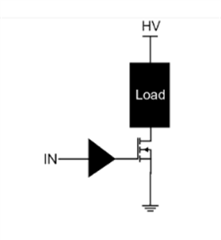
To my understanding, a gate driver is a type of power amplifier that accepts a low-power input from a controller IC and produces a high-current drive input for the gate of a high-power MOSFET as shown in the diagram below. 

Take the UCC2753x, for example, it says in the datasheet that this driver can drive motors, solenoids etc.

My question is, can I supply the  UCC2753x with an AC signal to amplify its current do drive an inductive load directly, as shown in the diagram below?

  1.  If its possible, what are the design steps.
  2. If its not possible, how do you suggest I drive a 1A current through a coil of inductance 10mH at frequency ranges of (15kHz to 35kHz).

Kind Regards,,,

  • Hi,

    Basically, the driver's output stage is a CMOS inverter made of FETs. The output is either off or on at full strength, with no in between. This makes it essentially a class-D amplifier. Therefore, the output resistance is not proportional to the input voltage or current, which is the case in a class AB type amplifier. If you wanted to amplify an AC signal directly, a class AB type amplifier would probably be the best choice, not this driver. However, you can still do it with PWM which is how a class-D amplifier recreates an AC signal.

     If its possible, what are the design steps.

    You need to break the input waveform into a PWM signal that replicates the sine wave. However, the driver is designed to drive a capacitive load, not an inductive one. It can supply a burst of current to charge the capacitive load, but when you drive an inductive load the current keeps increasing for the whole pulse width. This is basically a DC current, and the driver has a 12Ω impedance to DC current, which means a 12V drop. I don't think it is possible. 

    If its not possible, how do you suggest I drive a 1A current through a coil of inductance 10mH at frequency ranges of (15kHz to 35kHz).

    The best way to do this is like in your first image. You still need the PWM of the sine wave, but now the driver makes the low-side FET follow that PWM. Unlike the driver, the FET can handle large DC current. This is the standard way to do this as far as I am aware. Or you could try a different type of device/amplifier.

    Thanks,

    Alex M.

  • Thank you @Alex , I am looking into that...