This thread has been locked.

If you have a related question, please click the "Ask a related question" button in the top right corner. The newly created question will be automatically linked to this question.

USB-PD-CHG-EVM-01: Preferred power role: Power source Unexpected behavior.

Part Number: USB-PD-CHG-EVM-01
Other Parts Discussed in Thread: BQ25792, TPS25750, BQ28Z610, EV2400, BQSTUDIO, TPS25750EVM, BQ25798

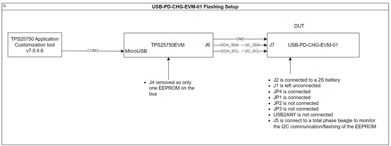
I am flashing the EEPROM on the USB-PD-CHG-EVM-01 with the following configuration provided from the TPS257570 Application Customization Tool v7.0.4.6:

{"questionnaire":{"version":"7.0.4.6","answers":[0,2,2,0,0,null,1,null,1,null,0,8.2,2,0.4,0.4],"options":{},"configID":"0000","vendorID":"0000"}}

In this configuration, I would expect the development board to Source power to a phone, and Sink power from a PD power supply from the attached 2S battery.

However, when I plug this configuration into a power supply, the battery does not charge. Here are the PD negotiation and BQ25792 I2C logs.PD Negotiation from wall power supply.csvBQ25792 I2C Communication from TPS25792 with wall power supply.csv

and, when I plug this configuration into a phone the phone does not charge. Here are the PD negotiation and BQ25792 I2C logs. This behavior repeats every second or so. In the log, I disconnect the phone after a few repeats.

PD Negotiation with phone.csvBQ25792 I2C Communication from TPS25792 with phone.csv

  • Hello Nate Martin,

    Thank you for reaching out to us and sharing the logs. 
    Please allow us time till Wednesday to analyze the logs and get back. 

    Best regards,
    Rohit. 

  • Hello Nate,

    Can you send the original total phase I2C log file and PD log file. I'm not able to decode the .csv file.

    Best Regards,

    Christian.

  • Good Afternoon Christian,

    We are using a Cypress PD Analyzer Tool for our PD negotiation logging. I hope this works for you. The .ccg3x file can be opened by the free "CY4500 EZ-PD Protocol Analyzer Utility" available on their website.

    Unfortunately, I did not keep the original log files, but re-recording the data produced the same results.

    DUT with Source only power supply.zip
    DUT with Phone.zip

    Thanks,

    Nate

  • Hello Nate,

    Thank you for this information, I'm looking into this issue and will provide you with an update when I get more information.

    Best Regards,

    Christian.

  • Hello Nate, 

    Can you send me the .JSON file, and can you explain how you flashed to the EVM.

    Best Regards,

    Christian.

  • Hi Christian,

    Here is the contents of the .json file:
    {"questionnaire":{"version":"7.0.4.6","answers":[0,2,2,0,0,null,1,null,1,null,0,8.2,2,0.4,0.4],"options":{},"configID":"0000","vendorID":"0000"}}

    Here is the zipped .json file:
    3630.config.zip

    As for flashing, I am using the TPS25750 Application customization tool v7.0.4.6. This is my setup:

    I have also verified the EEPROM's memory after flashing using an external EEPROM flashing tool. The flash memory read matches the Generated Full Flash Binary from the above config.json. Here is the generated full flash binary:

    Full Flash Binary.zip

    Nate

  • Hello Nate,

    Thank you for this information, I'm looking into this issue and will provide you with an update when I get more information.

    Best Regards,

    Christian.

  • Hello Nate,

    You selected the 45W as the maximum power that can be sourced , and 45W as the required sink power/consumed power.


    If you click on the advance configuration tab in the GUI, you can see the transmitted source/sink capabilities. 5V/3A, 9V/3A, 15V/3A

    In this PD log you can see that the phone selects to sink the second PDO which is 9V/3A. Your source is only able to supply 8.2V/2A.

    I recommend changing the maximum power that can be sourced and the the required sink power/consumed power. I would also recommend changing the transmitted Source and Sink capabilities.

    Best Regards,

    Christian.

  • This issue is not resolved. I accidentally clicked the resolve button.

    Is there a way to remove the resolved flag from messages?

  • Hello Nate,

    I do not see any way to remove the resolved flag from the messages, we can continue the discusssion on this thread. 

    This issue is not resolved. I accidentally clicked the resolve button.

    Did you change the maximum power that can be sourced and the the required sink power/consumed power. and change the transmitted source and sink capabilities?

    Can you send me an updated .JSON file and PD Logs?

    Best Regards,

    Christian.

  • That button is far to easy to click...

    I will try adjusting the power profiles today. Should have an update for you tonight or tomorrow.

  • Good Afternoon Christian,

    I have tried the following test setups/configurations:

    1. 15W Sink, 15W Source, preferred role Power Source, No USB Data, Charge config 8.2V/1A: Source15W.zip

    • ASUS COMPUTER MONITOR DOCK PORT - Battery does not charge. Why?
    • LAPTOP - Laptop charges at 5V 2.8A. Success!
    • PIXEL 3a - Phone charges at 5V 0.8A. Success!
    • SOURCE ONLY WALL CHARGER NO PD - Battery bank charges at 5V 1.8A. Success!
    • SOURCE ONLY WALL CHARGER WITH PD - Battery bank charges at 5V 1.8A. Success!

    2. 15W Source, 15W Sink, preferred role Power Sink, No USB Data, Charge config 8.2V/1A: Sink15W.zip

    The expected behavior for all of the following tests is that the TPS25750 negotiates power for the BQ25792 to charge the attached 2S battery:

    • ASUS COMPUTER MONITOR DOCK PORT - Battery does not charge. Why?
    • LAPTOP - Constant restarts of PD negotiation. Battery does not charge. Why?
    • PIXEL 3a - Battery does not charge. Why?
    • SOURCE ONLY WALL CHARGER NO PD - Battery charges. Success!
    • SOURCE ONLY WALL CHARGER WITH PD - Battery charges. Success!

    3. 27W Sink, 27W Source, preferred role Power Sink, No USB Data, Charge config 8.2V/1A: Sink27W.zip

    • ASUS COMPUTER MONITOR DOCK PORT - 9V negotiated, did not charge battery. Why?
    • LAPTOP - Battery Charges off laptop port for a few seconds then stopped. Why?
    • PIXEL 3a - 9V negotiated, did not charge battery. Why?
    • SOURCE ONLY WALL CHARGER NO PD - Battery charges 5V 1.8A. Success!
    • SOURCE ONLY WALL CHARGER WITH PD - Battery charges 9V 1A. Success!

    4. 27W Source, 27W Sink, preferred role Power Source, No USB Data, Charging config 8.2V/1A: Source27W.zip

    • ASUS COMPUTER MONITOR DOCK PORT - 9V negotiated temporarily. Battery did not issue a PS_RDY message after reaching 9V. Why?
    • LAPTOP - Battery bank and laptop seem to PR_SWAP a lot. Laptop doesn't charge off battery bank, but battery bank charges off laptop occasionally. Why?
    • PIXEL 3a - Phone does not charge off battery bank. Negotiation seems to be stuck in a negotiation loop? Why?
    • SOURCE ONLY WALL CHARGER NO PD - Battery charges 5V 1.8A. Success!
    • SOURCE ONLY WALL CHARGER WITH PD - Battery charges 9V 1A. Success!

    Based off the above data it seems there are two issues I am running into:

    1. Why does the battery bank (TPS25750+BQ25792) never charge off the ASUS COMPUTER MONITOR DOCK PORT no matter the configuration? The battery bank seems to constantly issue PR_SWAP requests when plugged into this device.
    2. Why cant the device output 9V @3A? The charge current limit setting does not limit the output current only input current. VBUS crashes before PS_RDY is sent by the TPS25750.
  • Hello Nate,

    Why does the battery bank (TPS25750+BQ25792) never charge off the ASUS COMPUTER MONITOR DOCK PORT no matter the configuration? The battery bank seems to constantly issue PR_SWAP requests when plugged into this device.

    I spoke with a collegue and he mentioned that a monitor dock  typically has a preferred source power role. In your first test both devices have a preferred source power role. This is causing the devices to repeatedly request a power role swap, and this cause the battery to not charge.

    In your second test with the ASUS COMPUTER MONITOR DOCK PORT, how long did you wait before you unplugged the device?

    Why cant the device output 9V @3A? The charge current limit setting does not limit the output current only input current. VBUS crashes before PS_RDY is sent by the TPS25750

    This may be a power limitaion from the battery side.

    Are you using an actual battery or a souce meter?

    What size battery are you using?

    Is the battery you are using capable of outputting 27W of power?

    Can you send me the TPS25750 0x40 PD_STATUS register values?

    Best Regards,

    Christian.

  • Thank you for your quick response!

    I spoke with a collegue and he mentioned that a monitor dock  typically has a preferred source power role. In your first test both devices have a preferred source power role. This is causing the devices to repeatedly request a power role swap, and this cause the battery to not charge.

    Is there a way to prevent this behavior? Can it be setup to force a particular power role with a GPIO button? Does the PD protocol have a way of indicating to the dock that its not a source of unlimited power?

    In your second test with the ASUS COMPUTER MONITOR DOCK PORT, how long did you wait before you unplugged the device?

    This test ran for 12Seconds. To confirm the behavior I just reloaded that configuration, rebooted the device, and plugged in the ASUS COMPUTER MONITOR PORT. Leaving it for >1 minute did not result in the device charging. 6406.Sink15W.zip

    This may be a power limitaion from the battery side.

    The battery is an actual lithium ion 2S pack that is capable of 5A output. I have been monitoring the pack with both an oscilloscope and the EV2400 interface to the BMS chip (BQ28Z610). I have not seen any drops in pack voltage. For these tests, pack voltage was ranged between 7.6V and 8V.

    Can you send me the TPS25750 0x40 PD_STATUS register values?

    I am working on a script/device firmware that will allow me to log the TPS25750 status registers. My plan is to poll these registers at 10Hz. Does this seem reasonable?

    The configuration I am most interested in is the 27W Source setup. I will rerun those tests and log PD_STATUS on the TPS25750.

    Thanks for your help,

    Nate

  • Hello Nate,

    I'm looking into this issue and will provide you with an update when I get more information.

    Best Regards,

  • Hello Nate,

    Will you send me the register values for the BQ25792 in these two conditions:

    1) 15W Source, 15W Sink, preferred role Power Sink, No USB Data, Charge config 8.2V/1A- ASUS COMPUTER MONITOR DOCK PORT 

    2) 15W Source, 15W Sink, preferred role Power Sink, No USB Data, Charge config 8.2V/1A:-SOURCE ONLY WALL CHARGER WITH PD 

    Can you also provide the Salaea I2C logs

    Best Regards,

    Christian.

  • Hello Christian,

    Here is the requested data. I wasn't sure what you meant by Salaea I2C logs, but I included the log of the PD_STATUS and STATUS registers on the TPS25750 polled at 10Hz.Sink15W with TPS25750 Reg Monitor.zip

  • Hello Nate,

    I wasn't sure what you meant by Salaea I2C logs

    We use the Salaea logic analyzer to decode the I2C communication between the PD controller and the BQ charger. I need the I2C logs to check if the PD controller is writing to the BQ Charger correctly, for this condition 

    1).115W Source,1 5W Sink, preferred role Power Sink, No USB Data, Charge config 8.2V/1A- ASUS COMPUTER MONITOR DOCK PORT 

    I'm not able to decode the I2C logs from a .CSV file

    Best Regards,

    Christian.

  • Hello Christian,

    Let me explain the files in that test zip file.

    For a given test, there are 4 logs.

    • The .log format is a recording from bqstudio of the battery protection chip we have (BQ28Z610). This chip is on a separate PCB, and can only disconnect the cells we are using from the TPS25750 board.
    • The .tdc file is a log of the EEPROM/BQ25792 I2C bus and is the file you are looking for to check if the PD controller is writing to the BQ25792 chip correctly. This can be opened with Total Phase Data Center.
    • The .ccgx3 is the PD log. This can be opened with EZ-PD Protocol Analyzer.
    • The .csv file is a decoded polling of the TPS25750 Slave I2C bus to monitor the PD_STATUS, and STATUS registers on the device. Values are in decimal, and correspond to the tables given in TPS25750 Host Interface Technical Reference Manual.
  • Hello Nate,

    Thank you for this information, I will give you an update after I review the information.

    Best Regards,

    Christian.

  • Hello Nate,

    I have created a sink15W project file: that I need you to test using the ASUS COMPUTER MONITOR DOCK PORT to see if this charges the battery. Please do not change any of the setting.If this does not work can you provide the PD logs.Sink 15W.zip

    Best Regards,

    Christian.

  • Good afternoon Christian,

    Apologies for the delay on this. I have tested the profile you sent without modifications. To load the json file I opened a new instance of the TPS25750 Application Customization Tool then loaded the file by clicking browse->open.

    It does not charge when plugged into the ASUS COMPUTER MONITOR DOCK PORT.

    Here is the data:
    TI Provided 15W Sink.zip

  • Digging further into this issue with the provided profile, it looks like the PPHV test point on the dev board USB-PD-CHG-EVM-01 is being held at ~9V when plugged into the Asus Computer Monitor:

    PPHV: 9V

    VBAT: 7.750V

    USB C VBUS: 5V

    BATTERY CURRENT: 0A

    USB C CURRENT: 0A

    When plugged into all other chargers I have available to me, it behaves normally:

    PPHV: 5V

    VBAT: 7.86V

    USBC VBUS: 5V

    BATTERY CURRENT: 1A

    USB C CURRENT: 1.8-2A

  • Hello Nate, 

    I'm speaking with a team member to gather further information on what could be causing this behavior.

    I have a couple questions, I want to check if the ASUS Dock is having an issue suppying power:

    Have you tried to source from the the ASUS Dock, without a battery attached to the charge EVM?

    I see that you also have a TPS25750 EVM, have you tried loading a sample project file on this EVM, and using this as the sink side?

    Is the ASUS Dock able to charge the laptop or PIXEL 3a phone that you have been testing with?

    Best Regards,

    Christian

  • All other devices I plug into the Asus dock are able to charge off the port. The Asus dock is a monitor with a multipurpose USB C port capable of USB PD 20V/3.25. It's model number is PA278CV.

    The devices I have checked are able to charge off this dock are:

    • Asus ROG Laptop
    • Pixel 7
    • Pixel 7 pro
    • HP Elitebook
    • Lenovo Yoga 730-13ikb
    • Pixel 3a
    • Anker 20000mah battery bank
    • Iniu 20000mah battery bank
    Have you tried to source from the the ASUS Dock, without a battery attached to the charge EVM?

    When I disconnect the battery it is able to negotiate 20V from the Asus dock.

    I see that you also have a TPS25750 EVM, have you tried loading a sample project file on this EVM, and using this as the sink side?

    I will try this. I have been avoiding this because the battery hookup to the TPS25750EVM (TP3) is in a terrible location. Far to easy to short battery to the surrounding components.

  • Hello Nate,

    I spoke with a team member and we want to know what the slave address is for the TPS25750 device?

    When I disconnect the battery it is able to negotiate 20V from the Asus dock.

    Are you using a different project file?

    Best Regards,

    Christian

  • By project file do you mean configuration? Which configuration should I be using?

    The slave address for the TPS25750 is 0x21.

  • Hello Nate,

    By project file do you mean configuration? Which configuration should I be using?

    The previous project file I sent to you had a maximum sink capabilty of 15W, I'm confused how the EVM negotiated 20V from the ASUS Dock.

    PPHV: 9V

    VBAT: 7.750V

    USB C VBUS: 5V

    BATTERY CURRENT: 0A

    USB C CURRENT: 0A

    In this test setup can you read the BQ25798 register, I suspect that the BQ device is getting stuck in OTG mode.

    This file I removed the source capabilities, so the BQ part should not go into OTG mode, so we can check if this is causing the charging battery issue. If this does not work please provide I2C logs, and PD logs

    .sinkTEST.zip

    Best Regards,

    Christian.

  • Hello Nate,

    PPHV: 9V

    VBAT: 7.750V

    USB C VBUS: 5V

    BATTERY CURRENT: 0A

    USB C CURRENT: 0A

    In this test setup if you clear EN_OTG on the BQ25789 device does it enable charging?

    In this previous project file do you see the same behavior PPHV=9V and VBUS=5V?

    2. 15W Source, 15W Sink, preferred role Power Sink, No USB Data, Charge config 8.2V/1A: Sink15W.zip

    Best Regards,

    Christian.