This thread has been locked.

If you have a related question, please click the "Ask a related question" button in the top right corner. The newly created question will be automatically linked to this question.

Efficient Load Sharing Solution for Dual 3.7V Li-ion Batteries

Other Parts Discussed in Thread: LM66100, LM66200, TPS22916

Dear Texas Instruments Team,

I am currently engaged in a project with a client that necessitates efficient load sharing between two 3.7V Li-ion batteries. In order to optimize power management and minimize losses during this process, I am seeking your guidance and recommendation on a suitable Texas Instruments IC or solution. Could you kindly advise me on the most appropriate component or solution for this application?

Thank you for your valuable assistance.

  • Hi Sharu,

    Welcome to E2E!

    What is current level for each of the battery path? 

    Best Regards,

    Rakesh

  • Hello,

    Thank you for your warm welcome and quick response.

    The current levels for each of the battery paths in my application are as follows:

    • Battery 1 Path: 10-30mA
    • Battery 2 Path: 10-30mA

    I should also mention that these batteries will be used in a game controller application. Please let me know if you require any additional information or if there are specific parameters I should consider when selecting an appropriate load-sharing solution.

    Best Regards, 
    Sharu

  • Hi Sharu,

    Unfortunately we do not have a load sharing solution right now with ideal diode controllers or power swithces.

    But I am interested to understand why load sharing is so important here considering the total load current is very low 20-60mA

  • Hello Praveen,

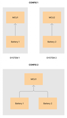
    We are presently dealing with two distinct devices, each equipped with its own microcontroller (MCU) and battery power supply. For reference, we'll designate these systems as System 1 and System 2.

    However, we are exploring the possibility of combining these two devices in a manner that leverages the combined power of both batteries to supply a single MCU from System 1. It's worth noting that when these devices are combined, there exists the potential for one of the device's batteries to possess a higher voltage level than the other. Consequently, our objective is to employ ideal diode ORing to utilize power from the higher voltage battery until equilibrium is reached, at which point both batteries will be discharged equally.

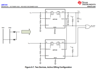
    I've provided a simplified diagram to illustrate this concept

    We would greatly appreciate any feedback or chip recommendations you may have regarding this design. Your insights and expertise in this matter would be invaluable.

    Thank you in advance for your assistance.

    Best regards,
    Sharu

  • Hi Sharu,

    Thanks for sharing more information on the requirement. From your description we can understand that you just require an ORing controller/device. 

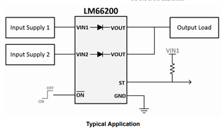
    For the voltage and current levels in your application 3.7V and 60mA, you can consider using 2x LM66100 or 1x LM66200 to realize ORing configuration between two power supplies

  • Hello Praveen,

    Indeed, the shared components aligns with our requirements, and we appreciate your guidance on that.

    I have a few questions on this:

    I looked into the LM66200 datasheet but was unable to locate information pertaining to this specific scenario that is covered in LM66100. This scenario is something that would occur quite often in our application.


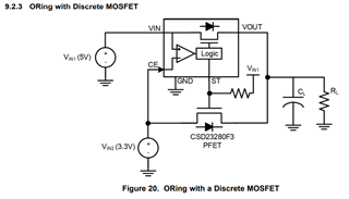
    Moreover, I'm contemplating an alternative approach involving a single LM66100 and an external MOSFET, as depicted below.

    This would simplify the design, but I am curious about potential drawbacks, especially considering that the batteries may eventually reach the same voltage level.

    Your insights on this matter would be greatly appreciated.

    Thank you for your assistance.

    Best regards,
    Sharu

  • Hi Sharu,

    I will let the team supporting LM66100 comment on your queries.

  • Thanks Praveen.

    Hi Sharu,

    It looks like you would run into issues with the device oscillating between input batteries when their voltages are very close. Before I start discussing solutions to this issue with you, I want to run another idea past you to see if it would better fit the application.

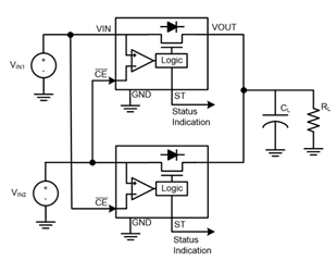
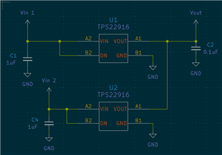
    The LM66x00 devices only allow one input to be active at a time. Would you be able to use a load switch that has reverse current blocking, such as the TPS22916 or TPS22948? Two devices could be used in parallel, and when one input is greater than the other, the lesser input's device could activate reverse current blocking. When the two batteries' voltages are equal, the reverse current blocking would be deactivated and both inputs would be active simultaneously. It would be similar to the setup described below:

    Would this solution work for your application, or do you prefer using the LM66100?

    Thanks,

    Patrick

  • Hello Patrick,

    I would like to express my appreciation for your prompt response.

    If I understand correctly, you are suggesting an approach similar to the image below

    This indeed appears to be a smart solution, and I see no immediate reasons why it should not be applicable to our particular case.

    In light of this proposal, we are considering conducting tests involving both the TPS22916 and LM66100 to ascertain which option aligns best with our requirements. Both options appear promising for our application.

    Thank you for your insights and guidance.

    Best regards,
    Sharu

  • Hi Sharu,

    Yes, that circuit is the accurate implementation of what I mentioned above.

    Please let me know if you have any more questions, or if we can help with anything further.

    Thanks,

    Patrick

  • Hi Patrick,

    Nothing else as of now. 
    Thank you, Patrick and everyone else who was involved in this thread.

    Best regards,
    Sharu

  • Hi,

    I had a problem similar to this circuit.

    Please see my post from the link

    e2e.ti.com/.../lm66100-lm66100-ideal-diode-is-not-working-as-expected