This thread has been locked.

If you have a related question, please click the "Ask a related question" button in the top right corner. The newly created question will be automatically linked to this question.

BQ40Z50: Wake up battery via charger

Part Number: BQ40Z50
Other Parts Discussed in Thread: BQ24800, BQ40Z60, BQ24800EVM

Hello fellow engineers,

We are currently redesigning a battery with charger integrated using the BQ40Z50 gauge and BQ24800 charger IC.
Our existing battery uses the BQ40Z60 which can always be waked up by applying a voltage to the charger input (i.e. when cells are inserted the first time, when the chip is in sleep/shutdown).

When connecting the battery cells to the BQ40Z50 EVM for the first time, we noticed the system could only be awoken by pressing the physical WAKE pushbutton. It was not able to wake the system up by applying a charging voltage to the BQ24800.

In the final design, the pack should be able to wake up when the external charger voltage is connected to the BQ24800. How can we implement this?

  • Hello Svenn,

    The BQ40z50 is waked up from shutdown by applying a voltage at the PACK pin greater than a Vstartup threshold specified in TRM (typically ~3V). 


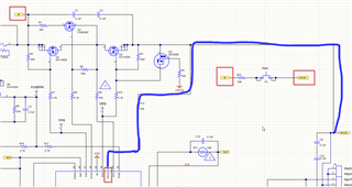
    The action of pressing the WAKE button in the Evaluation Board bypasses the protection FETs and assuming that the battery is attached, it will wake the device. See below.


    In the final design, the pack should be able to wake up when the external charger voltage is connected to the BQ24800. How can we implement this?
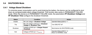
    I am not sure how you connect the BQ24800 charger IC, but if this is connected to PACK+ from the BQ40z50 EVM, it will apply a voltage high enough to wake the device. It is important to know that the device will enter shutdown mode again if the min cell voltage is less than Shutdown Voltage (see the first picture).

    Regards,
    Jose Couso

  • Hi Jose,

    I understand the BQ40Z50 wakes up when applying a voltage >Vstartup to the pack pin of the BQ40Z50.
    The output of my BQ24800 EVM is indeed connected to the PACK+ pin of the BQ40Z50 EVM. When I apply a voltage (20V) to the BQ24800, its output stays at 0V until the BQ40Z50 sends a charging voltage and current through the SMbus. It will never get any SMbus command since the BQ40Z50 is sleeping so the system can never wake up except by pushing the button. Everything including charging works fine once the system is awake.

    Is there a way to implement a solution where the charger voltage can wake up the system?

    Regards,
    Svenn

  • Hello Svenn,

    You may need to configure the bq24800 to output a voltage to wake the bq40z50.

  • Hello Shirish,

    Can you please give me more information on this solution? How should I configure the BQ24800 to get an output voltage to wake the BQ40Z50?

    Regards,
    Svenn

  • Hello Svenn,

    I will assign this thread to the charger expert.

    Regards,
    Jose Couso

  • Hi Sven,

    I am looking into this and will get back to you by mid-week.

    Best Regards, 

    Aya 

  • Hi Aya,

    Do you have any updates on this subject? Thanks.

    Regards,
    Svenn

  • Hi Svenn,

    Thank you for reaching out!

    Apologies for the delay here.

    I am going to run some tests and let you know the results by Wednesday. My initial thoughts is that you probably need a separate MCU to enable charge to get VBAT to charge up.

    Best Regards, 

    Aya Khedr 

  • Hi Aya,

    Do you have any updates on the solution? Our system is designed as a Smart Battery (as figure 1-2 in your Autonomous Smart Battery guide) without an MCU.

    Kind regards.

  • Hi Svenn, 

    I understand the autonomous smart battery design is implemented without an MCU but this would only work in the case when the battery gauge (host) is awake to communicate to the charger and set important register values. 

    Upon start-up, the BQ24800 is set to its default conditions: Charge Current (reg0x14) = 0A and Charge Voltage (reg0x15) = 0V. Changing these register values increase the voltage on VBAT (output) but each time the device is power-cycled, the register values are set back at default. For this reason, an MCU would be needed to set the register values to enable charge and charge VBAT. 

    Please let me know if you have additional questions/concerns. 

    Best Regards, 

    Aya Khedr 

  • If I understand correctly, if I want to make a smart battery, I have to ensure that the battery never goes into shutdown, otherwise it will never work again?
    Since there may be a way the BQ40Z50 gets a power on reset after which it will enter shutdown mode, I need way to leave this mode.

    Using a microcontroller is way too expensive for only waking the device in an exceptional situation. Is there a way to properly implement a wake up solution in hardware?

  • Hi Svenn, 

    Unfortunately, the BQ24800 default values cannot be changed. Without host interaction, it will stay at these default values. 

    Is it possible to prevent the BQ40Z50 from entering sleep mode? I will reassign to the battery gauge team to get their input here. 

    Best Regards, 

    Aya Khedr 

  • Hi Svenn / Aya,

    If I understand correctly you want to integrate the BQ40Z50 and the BQ24800 to replace the BQ40Z60. 

    On the BQ40Z60 you aply a charge voltage to wake up the battery from shutdown and want to accomplish the same for the combination BQ40Z50 - BQ24800.

    Looking at the schematics of BQ40Z50EVM, you wake up the battery by pressing the wake-switch - putting a voltage on pin 27, PACK, of the BQ40Z50. Since the switch is not applicable in the final design, there have to be antoher way to get a 'wake-up' voltage on that pin.

    If you want to wake up the battery via the charger but the BQ24800 is not operational (default values) the easiest way is to connect the BQ24800 input, 'Vin' on the BQ24800EVM, to pin 27, PACK, from the BQ40Z50.

    I suggest a diode + resistor from 'Vin' (BQ24800EVM schematic) to R12 (BQ40Z50EVM schematic) and adding a diode from 'PACK+' to R12 on the BQ40Z50EVM. 

    So if the BQ40Z50 is in shutdown mode it remains there till there is an input voltage applied to the BQ24800, going through 'diode + resistor' to R12. This diode prevents leakage current from 'PACK+' to the BQ24800 input when there is no voltage applied and the battery is active.

    The diode from 'PACK+' R12 prevents current from the charger input (Vin) going straight to 'PACK+'.

  • Hi Aya,
    I think it is impossible to prevent the BQ40Z50 from entering shutdown mode, since it goes into shutdown mode after a Power On Reset event.
    How would TI suggest me to implement the 'smart battery' (without an MCU)? Should I use an other charger or may the solotion Robert Ploeg suggests work? 

    Thanks.
    Svenn

  • Hi Svenn,

    All the BQ40z50 requires is to have a temporary voltage at PACK pin to wake up the device. It looks like Robert's solution works. Robert might have implemented it himself. 

    Regards,
    Jose Couso

  • Hi Jose,

    I made the modification Rob and you suggested on your BQ24800 EVM which is connected to the BQ40Z50 EVM.

    I connected the charger input voltage via a 10k resistor and diode to the pack pin of the BQ40Z50. I also added a second diode between the pack pin and the existing pack pin resistor to prevent the first diode charging the battery.

    The charger presence detection when the pack is in shutdown works, but the gauge now reports a lower 'PACK pin voltage'. As expected the 'PACK pin voltage' drop is equal to the voltage drop acros the diode which is about 180mV.

    Does this affect the operation of the BQ40Z50 in any way since it now measures the wrong voltage? Are any wrong assumptions/calculations now being performed internally?

    Update: when the charger input voltage (thus the voltage on the diode connected to the PACK pin) is raised above Vbat+CHGV:Threshold*amount of cells (i.e. 22V), the gauge detects a pack voltage higher than the inteded charging voltage which trips the CHGV bit that stops the charging. How to solve this without bypassing protections?

    Kind regards,
    Svenn

  • Hello Svenn,

    Does this affect the operation of the BQ40Z50 in any way since it now measures the wrong voltage? Are any wrong assumptions/calculations now being performed internally?

    The gauge will measure the voltage difference across the sense resistor and will report current based on V/R. Does the gauge read any current greater than 0mA during relax? The only concern will be if the difference in voltage in the sense resistor is high enough to make the gauge change to charge or discharge status while in RELAX.

    How to solve this without bypassing protections?

    You will probably have to increase the CHGV:Threshold or the CHGV:Delay if it only happens for a few seconds.

    Regards,
    Jose Couso