Other Parts Discussed in Thread: TPS38900X-Q1, TDA4VH, TPS6594-Q1
Hello,
We are evaluating the <TPS38900xQ1_SFFS545_Functional_Safety_Manual_May>, and here are the questions about the AOU:
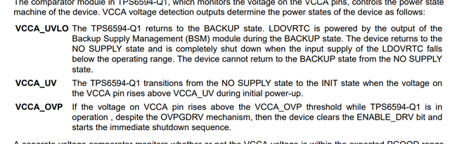
1. [SA-3] in chapter 4.3 request the integrator to transit the system and TPS389006 to the safe state when the input voltage of TPS389006 is error.
How can the TPS389006 transit to the safe state when the input voltage is under-voltage? Do you have any suggestions on the design ?
2. [SA-4] in chapter 4.3 reques the MCU to read the error status of the TPS38900x-Q1 when the TPS38900x-Q1 sends an interrupt signal to the MCU.
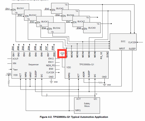
①Where is the interrupt signal(also referred as NIRQ pin) connected? Is the MCU same as the MCU domain in TDA4VH?
②If the answer is 'Yes', the MCU domian cannot run correctly cause the input power rail is abnormal as detected by the TPS389006, therefore the MCU domian may not react correctly about the interrupt signal and read the error status correctly;
③If the Answer is 'NO', which IC havs the ability to read the error status. since the interrupt from the 389006 leads the system in the safe state.
3. [SA-5] and [SA-6] in chapter 4.3 also mention the MCU-software. So does the MCU here refer to the MCU domain of the TDA4?