This thread has been locked.

If you have a related question, please click the "Ask a related question" button in the top right corner. The newly created question will be automatically linked to this question.

TPS61021A:TPS61021A-PWR723 EK VOUT DROP.......

Part Number: TPS61021A
Other Parts Discussed in Thread: TPS2113, TPS631000

HI.

TPS61021A-PWR723 EK is being tested.

TPS61021A-PWR723 EK DATASHEET 2page is said to be possible up to 1A when VIN=1.2V/VOUT=3.3V

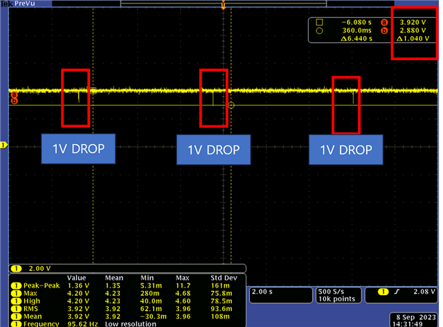
I changed EK R3 to make VOUT=3.9V and applied VIN=1.5V as a power supply. At this time, the load current is MAX400mA.

However, as shown in the attachment below, 1V DROP is periodically generated.

The same applies to adding CAP to C6.

The output current seems to be insufficient. Is 1A correct?

It seems to be less than 400mA.

BR.

KWON.

  • Hi Kwon

    I'm afraid your time scale is too large for us to find out what's going on. Can you change the time scale until the drop period fills over half of the screen. Also, it'll be better if you can place Vout , SW, IL, Vin waveform in the same screen.

    Best Regards,

    Travis

  • Hi. Travis.

    Each waveform(VIN/VOUT/SW) at a MAX 400 mA load (RF MOULE). IL is not measurable. The waveform below is an rf module connected to ek board.

    When the resistor 10 ohm is mounted (390 mA), the output voltage is DROP from 3.9 V to 1.7 V.

    It is the same even if you replace the U1 (TPS61021) with another one. What is the problem?

    Is the input current insufficient?  The power supply uses E3649A and can use up to 1.4A.

    One more...

    The last thing I'm trying to do is 1.5V BATT -> TPS61021 3.7VOUT -> MUX TPS2113 -> BUCK-BOOST TPS631000

      ==> Battery only for a short period of time when there is no main voltage. MAX 400mA.

    Please also check if there is a problem with the circuit below.

    Once the EK test is completed, it will be configured as above.

    Thanks.

    Best Regards,

    KWON.

  • Hi Kwon,

    Seems that your input voltage is below 1V even before the drop occurs. Have you tried changing another supply with a bigger current limit? 

    About your schematic, the boost part seems to be okay. But I believe you know that the input voltage will drop as the battery discharges . And the internal resistance of the battery will cause a voltage drop on the boost input, too. So please make sure that the battery voltage will not drop below 0.5V under worst conditions.

    Best Regards,

    Travis

  • Hi Travis.

    The power supply voltage seems to have dropped.

    Power supply tested 1.5V supply, EK output 3.3V, resistance load.

    At 10 ohm load (3.3/10=330mA), the input current 1A and the input voltage are DROP from 1.5V to 1.1V.

    EK USER GUIDE (3PAGE) states that the efficiency is 90%. However, during the resistance load test, the input current is more than 3 times the load current.

    Why is the input current more than 3 times the load current?

    Is there a formula or graph for calculating input current?

    If the output current is 1A when the EK USER GUIDE 2PAGE, VIN=1.2V, the input current is 3A.

    EK USER GUIDE 2PAGE , When VIN=1.2V, Io=1A, the input current will be 3A.

    It seems like AA 1EA is not enough current, but does DATASHEET alkaline mean more than 2EA in parallel?

    Best Regards,

    KWON.

  • Hi Kwon,

    Since your input voltage have dropped, it is normal that the input current will rise. Please view Datasheet equation1 to calculate the input current.

    The number of battery depends on the customer's overall consideration on cost, space, current capability and battery capacity. From my experience most customer will not use 1 battery for 3A current.

    Best regards,

    Travis

  • Hi Travis.

    Usually, a voltage drop occurs when there is not enough output current.

    As mentioned earlier, the power supply can be used up to 1.4A.

    It is 330mA(3.3v/10ohm) resistance load.

    Therefore, it is not understandable that the voltage DROP is issued.

    And, Equation1 is Iout. Is it the same as Iin?

    Best Regards,

    KWON.

  • Hi Kwon,

    I don't know why your power supply goes wrong since it's not our product. I recommend leaving a bigger margin and use a supply with bigger current limit. You can check the input voltage and see whether the voltage drops under lignt load or open load. If the voltage only drops when the load current increases, then you can be sure that your supply cannot afford that current. Maybe the current limit of that supply is smaller than its nominal data.

    Equation1 depicts the relationship between Iout and IL. Neglect the ΔIL(p-p), replace ILim with Iin, you can get the relationship between Iout and Iin.

    Best Regards,

    Travis