This thread has been locked.

If you have a related question, please click the "Ask a related question" button in the top right corner. The newly created question will be automatically linked to this question.

TPS65987D:Power supply is fixed to the source, and data would like to configure a DRP with priority given to DFP.

Part Number: TPS65987D
Other Parts Discussed in Thread: TPS65987,

Dear Support team,

The product we are developing a Linux OS host machine. However, only under certain conditions, we want to connect it to a PC (Windows) and receive data via USB3 port.

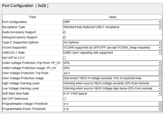
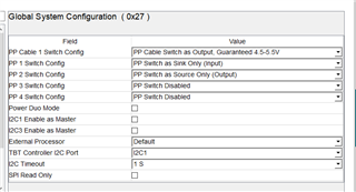
As a Power Delivary, we want to fix the power supply to the source as it does not consist a sink, and the data consist to the DRP with priority on DFP. Is my desired configuration possible?

I created the attached project but it did not work as expected.

VBUS conflicts with VBUS on the PC, is this a problem?

I consider that when our product is UFP, the USB 2.0 D+ and D- will conflict as both the PC and our product are hosts, is this a problem?

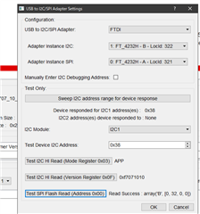
Attached is a log file of the connection to the PC.

0310.DRPtest_log_to_WinPC.csv0310.230908_test_for_DRP_from_NewProject.pjt

  • Hi,

    I am taking a look at this. Please give me some time to look at your configuration and provide a response.

    Best,

    Alex

  • Hi,

    I took a look at your project file and one of the hidden bits "process swap to UFP" was not set properly in the 0x29 Port Control register. I have set this bit in the project file attached. When this bit is not set, the PD will not process a swap from DFP to UFP that was initiated by the far-end device, in this case the windows PC. Additionally, the configuration was set to always initiate a swap to DFP, which I believe may also be an issue. This is also corrected. Please try this project file without changing any configurations and let me know if it works.

    0310.230908_test_for_DRP_from_NewProject_modified.pjt

    The configuration in this project file should achieve your desired behavior:

    • PD power role fixed to source
    • PD data role is able to swap to DFP and is able to swap to UFP. 

    The PD controller in the PC will know during power negotiations that the PD on your linux host machine cannot support sinking power, therefore, the PC will not source power on VBUS.

    When your PD on the Linux host machine swaps to a Data UFP role to receive data from the PC, the PD is no longer a data host but a data sink. This swap ensures no conflict in USB communication.

    Best,

    Alex

  • Hello Alex-san,

    Thanks for your project file.

    But after flashing your project file and connect to WondowsPC, it detected the cable for a moment, but then my TPS65987 do not detect the cable connection. When I connect the cable, the debug status remains no connection.

    And when I flash my previous power source and data DFP projects, it does not detect the cable connection.

    So the TPS65987D might be destroyed. It seems something went wrong with the interface that connects to the connector but I2C and SPI I/F is active.

    Different from the issue in this case, is there any way to verify that the device is working correctly?

    Best Regards,

    Yukio Oyama

  • Hi Yukio-san,

    Please try this project file instead. It may be a configuration issue if only a cable connection is not detected.

    DRP_PowerSourceOnly_0913.pjt

    If you still see the same issue, please take a snapshot of the PD registers in debug mode and send it here. To do this, enter debug mode in the debug tab. Then once in debug mode, click on the debug tab again to see the option for "take a snapshot".

    Best,

    Alex Liu

  • Hello Alex-san,

    New project file did not detect the connection either. SnapShot attached.

    230914.zip

    Best Regards,

    Yukio Oyama

  • Hi Yukio-san,

    It looks like no cable or connection is detected, and no cable switches are enabled. This means the PD is not able to see the far-end device connected.

    Can you check if your I2C connection to the PD still works? You can do this by using the GUI and sweeping for the device under the adapter tab. Use the pop up window to sweep for the PD using I2C and read the mode register afterwards. The sweep should succeed and the mode should be APP. This would indicate a booted up PD and no issues there. 

    Best,

    Alex

  • Hello Alex-san,

    That's not a problem.
    When I connect to WinPC, the debug status is no connection - > unplug the cable from the PC - > on the tool, I exit debug mode and check the connection with the adapter test, but I2C is still alive.

    I always watch the status in debug mode, but since the test when I flashed "DRP_PowerSourceOnly_0913.pjt" and connected to WinPC, the PD behaves abnormally.

    It happens that I2C does not work right after starting TPS65987. At that time, when I connect the USB-C-PD-DUO-EVM Sink board, nothing responds. After several times of start-up, I2C may work, and I proceed with the test at that time.

    I think that the I2C working and not working means that the device has been damaged. Or some parameter causes this problem?

    Best Regards,

    Yukio Oyama

  • Hi Yukio-san,

    When you initially connect the PD to the WinPC, you need to go to the adapter tab and sweep I2C address range for device response prior to entering debug mode. This is necessary everytime you unplug the PD from the WinPC and plug it back in using micro-USB cable. Otherwise, the GUI tool will not find the PD controller. This could be why you see an inconsistent connection with the GUI tool.

    I just took a look at your configuration register snapshot you sent, and it looks like the configuration changed from the project file I sent. I see that the port is actually disabled and in the source PDOs, the only source PDO is at 0A max current. I am not sure what happened there. It could be just a communication issue, as I have seen similar cases in debug mode. Can you send me a screenshot of registers 0x27 Global System Configuration and 0x28 Port Configuration not in debug mode. I just want to confirm the settings are still correct in your project.

    Best,

    Alex

  • Hello Alex-san,

    I attached it,

    Best Regards,

    Yukio Oyama

  • You might also want to check you ADCIN resistor divider setting. If that doesn't match then the configuration would not load properly.

  • Hi Yukio-san,

    When you plug in the type C cable and the PD reports no connection, does the status register say plug present at least? 

    I tested the "DRP_PowerSourceOnly_0913.pjt" configuration on two EVMs I have and it does work properly. The far-end device can be detected and the data role can be swapped to UFP.

    Are you testing this with a TPS65987D in your system or are you using our EVM?

    A couple things to remember:

    • Please ensure the ADCIN settings are correct (switch S4 on the EVM) for the desired I2C address.
    • Also, please make sure you go to the adapter tab of the GUI and sweep for the PD controller before you try and flash to it.

    Best,

    Alex

  • Hello Alex-san,

    The ADCIN setting is set every time and the adapter is swept every time. I am using our system (custom board) and the status is no plug.

    However, now even the DFP project I was using before considering DRP no longer works.

    I think some failure occurred in the TPS65987D during the DRP testing. I will try to replace the device but it will be difficult and will take a period of time.

    Best Regards,

    Yukio Oyama

  • Hi Yukio-san,

    It could be a device failure since I do see the project configuration working on my end.

    Two more things you can check if you would like:

    1. Is the PD controller still able to source VBUS? Probe VBUS from the PD controller.
    2. Is any PD traffic occurring at the port? If you have a PD analyzer from TotalPhase or EZ-PD, you can hook it up between the type C port in your system and the far end device to see if any PD traffic is being exchanged.

    If both of the above are "no", there is a good chance that there could be something wrong with the PD controller IC.

    Please let me know if you have any difficulties obtaining parts from TI.com.

    Best,

    Alex

  • Hello Alex-san,

    My device replacement has not been successful; I am trying again to replace it because FTDI will not connect.


    I have a question about DRP operation:

    When the TPS65987D switches to UFP, how should the USB2.0 (D+/D-) signal be handled? Perhaps the USB2.0 port should use a port that supports OTG and switch the ID pin using the "Port0 UFP DFP Event" on the GPIO?

    My circuit is not configured to switch USB2.0 ports.

    USB3.0 ports have separate Tx and Rx lines so there is no signal conflict whether it is DFP or UFP, but USB2.0 does not change its orientation when switched to UFP. So the signals conflict with each other as hosts.

    Does this have anything to do with your project file not working as expected in my environment?

    Best Regards,

    Yukio Oyama

  • Hi Yukio-san,

    The D+/D- signals for USB2.0 are not handled by the PD controller directly. These signals are typically routed from the connector to a USB2.0 2:1 MUX for plug orientation, then to the USB host. USB2.0 D+/D- signals are bidirectional, unlike Tx/Rx signals in USB3.0 which are unidirectional. Even with DRP enabled, the PD controller will configure itself as DFP or UFP upon connection with the far-end device, and the far-end device will configure itself as the opposite. This is through the CC signals. Both PD controllers on the Linux host machine and far-end will not be a data host at the same time.

    Can you check if the PD and your system still work with the unmodified original project file you sent me? If it does work, then the project configuration I sent may not be suitable for your environment. However, if the original project configuration also does not work, then there is a different issue.

    Best,

    Alex