Hi support team,
TPS65911AA2NMAT outputs other than VRTC are not output.
The situation is similar to the "Original question" above.
Has the EEPROM program problem improved?
Please let me know the measures.
Regards,
Dice-K
This thread has been locked.
If you have a related question, please click the "Ask a related question" button in the top right corner. The newly created question will be automatically linked to this question.
Hi support team,
TPS65911AA2NMAT outputs other than VRTC are not output.
The situation is similar to the "Original question" above.
Has the EEPROM program problem improved?
Please let me know the measures.
Regards,
Dice-K
Your device is booting into the OFF state (based on section 6.5.1 of the datasheet), which means a 'Device POWER ON disable' condition in present (section 6.5.1.2 of the datasheet).
Due to the EEPROM settings in the TPS65911A User's Guide, the only reason the device isn't transitioning to POWER ON is because of one of the following (from datasheet):
6.5.1.2 Device POWER ON Disable Conditions
Device POWER ON disable conditions are as follows:
• PWRON signal low level during more than the long-press delay: PWON_LP_DELAY (can be disabled though register programming). The interrupt corresponding to this condition is PWRON_LP_IT in the INT_STS_REG register.
• Or die temperature has reached the thermal shutdown threshold (THERM_TS = 1).
• Or DEV_OFF or DEV_OFF_RST control bit is set to 1 (DEV_OFF value is cleared when the device is in OFF state).
Additionally, from section 3.2 of the User's Guide, do you have the BOOT pin set to high?
Kind regards,
Conner Gillette
Hi Conner,
Thank you for your reply.
Does "PWON_LP_DELAY" mean "PWON_LP_OFF"?
EEPROM data has not been changed since shipment.
Since PWRON is open, I don't think it falls under "PWRON long-press."
I don't think temperature is an issue.
BOOT1 is connected to VRTC.
I think it will start if I apply 5V to V5IN and VCCx, but do I need any other settings or operations?
I would like to send you the schematic via Private Message, so I send you a friend request.
Best regards,
Dice-K
Here is the definition of PWON_LP_DELAY:

I've accepted your request. Please send me the schematic at your earliest convenience, and I will review it.
Kind regards,
Conner Gillette
Hi Conner,
The following settings probably solved the problem.
・PWRON: Floating
・PWRDN: Pull down
The PWRDN pin is set to power down when it is high.

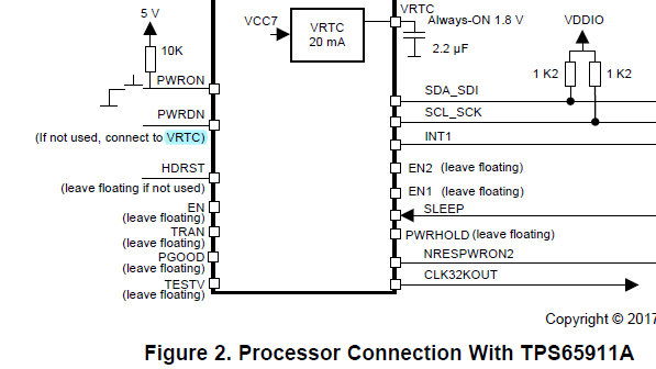
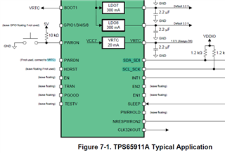
Figure 2 of SWCU187A and Figure 7-1 of SWCS049S are incorrect.


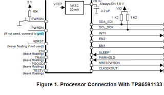
PWRDN should be written as "If not used, connect to gnd" like TPS6591133.

Is it okay to connect PWRDN directly to GND without using a pull-down resistor?
Also, in Figure 2, PWRON is a 5V pull-up.
Is there no problem with floating?
(Is internal pull-up valid?)
Best regards,
Dice-K
Thank you for providing this detailed information. I will review the associated setting and the technical documentation and update you this coming Monday.
Regards,
Conner
After reviewing the User Guide for the TPS65911A and the datasheet, I can confirm the following:
I will put in a request to have the user guide updated to reflect the correct configuration.
Kind regards,
Conner Gillette